Control system for tension tester

A tensile testing machine and control system technology, applied in electrical program control, program control in sequence/logic controller, measurement device and other directions, can solve the problems of signal distortion tensile testing machine testing accuracy, etc. Accuracy, simple circuit structure effect

Inactive Publication Date: 2019-01-29
鹤壁市质量技术监督检验测试中心
View PDF1 Cites 0 Cited by
  • Summary
  • Abstract
  • Description
  • Claims
  • Application Information

AI Technical Summary

Problems solved by technology

[0005] In view of the above situation, in order to overcome the defects of the prior art, the purpose of the present invention is to provide a tensile testing machine control system, which has the characteristics of ingenious design and humanized design, and effectively solves the problem of signal distortion caused by mutual communication between PLC and computer. , Attenuation affects the testing accuracy of the tensile testing machine

Method used


Image

  • Control system for tension tester
  • Control system for tension tester
  • Control system for tension tester

Examples


Embodiment 1

[0016] Embodiment 1, a tensile testing machine control system, including sensors, PLC, servo system, computer, the PLC output control signal to the servo system, the servo system provides power to drive the tensile mechanism of the tensile testing machine, etc. to carry out various materials Mechanical performance tests (such as tension, compression, bending, shearing, tearing, peeling, etc.); the sensor converts the signal when the tensile testing machine performs mechanical performance tests on various materials into electrical signals (such as the load cell will The tensile force borne by the material is converted into an electrical signal), which is transmitted to the PLC as a feedback quantity; the PLC and the computer communicate with each other to realize human-computer interaction, specifically, the human outputs the control signal to the PLC through the computer, and the PLC outputs the control signal to make the tensile testing machine perform mechanical testing. In t...

Embodiment 2

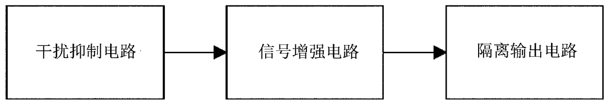
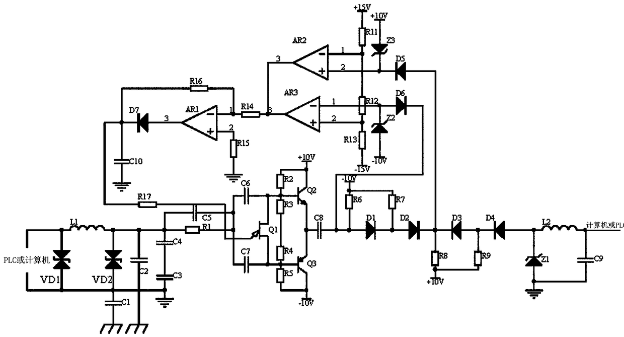
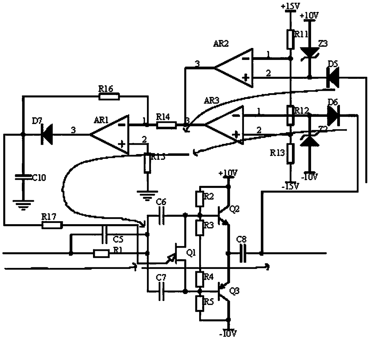
[0018]Embodiment 2, on the basis of Embodiment 1, the signal enhancement circuit receives the output signal of the interference suppression circuit, and the corner frequency generated by the RC parallel circuit composed of the resistor R1 and the capacitor C5 only allows the frequency component of the output signal of the interference suppression circuit Through the capacitors C6 and C7, they are respectively coupled to the base of the complementary amplifier composed of the transistor Q2 and the transistor Q3, wherein the resistor R2-resistor R4 provides the bias voltage for the complementary amplifier, and the complementary amplifier is amplified and then output through the capacitor C8. In order to make the amplification After meeting the requirements of the signal amplitude, the difference signal is output by the dual comparator with operational amplifier AR2 and operational amplifier AR3 as the core. The conduction angle of the unijunction transistor Q1 is used to adjust t...

Embodiment 3

[0019] Embodiment 3, on the basis of Embodiment 2, the isolated output circuit uses diode D1 in series with diode D2 to isolate the passage of interference signals below -10V, and diode D3 in series with diode D4 to isolate the passage of interference signals above +10V, which allows the amplitude When the useful signal of -10V-+10V passes through, the noise interference that does not overlap in time is suppressed, and finally the LC filter circuit composed of the voltage regulator Z1, the inductor L2 and the capacitor C9 filters the undisturbed and meets the signal amplitude. The stable and stable signal is transmitted to the computer or PLC, wherein resistor R6-resistor R9 is a pull-up resistor, including diode D1, resistor R6, the positive pole of diode D1 and one end of resistor R6 are connected to the output signal of the signal enhancement circuit, and the negative pole of diode D1 Connect the anode of diode D2 and one end of resistor R7 respectively, the other end of res...


PUM


Abstract

The invention discloses a control system for a tension tester. Interference suppression circuits suppress electromagnetic interference by electromagnetic interference suppression circuits. Decouplingcapacitors eliminate crosstalk among signals. LC filter circuits filter out unwanted noise signals. Differential noise suppression circuits enter signal enhancement circuits after suppressing differential mode interference. The signal enhancement circuits adopts a complementary amplifier composed of a triode Q2 and a triode Q3 for amplification, and the conduction angle of a single junction transistor Q1 is changed through the difference signals outputted by a dual comparator and then stably outputted after being inverted and held by an operational amplifier AR2, so that the amplified signalsof the complementary amplifier are adjusted, and the problem of attenuation in signal transmission is solved. Finally, the steady signals which are undisturbed and satisfy the signal amplitude are transmitted to a computer or PLC after being isolated by the isolation output circuit , being stabilized and being filtered, thereby improving the test accuracy of the tension tester. The problems that the PLC and the computer communicate with each other, and the signal distortion and attenuation influence the test precision of the tensile tester are effectively solved.

Description

technical field [0001] The invention relates to the technical field of tensile testing machines, in particular to a tensile testing machine control system. Background technique [0002] Tensile testing machine, also known as universal material testing machine, is used to test mechanical properties such as static load, tension, compression, bending, shearing, tearing, peeling and other mechanical properties of various materials. Testing machine, with the development of automation, the application of computer system tensile testing machine is born, the working process is human through the computer to send the control signal to PLC, the PLC control system servo drives the deformation mechanism of the tensile testing machine (such as pulling / compressing mechanism ) to pull up / compress the material, the sensor converts the test signal (pull / compress signal) into an electrical signal, and transmits it to the PLC as a feedback amount, and the PLC feeds back to the computer, and the...

Claims


Application Information

Patent Timeline
Patent Type & Authority Applications(China)
IPC IPC(8): G01N3/02G05B19/05
CPCG01N3/02G05B19/05
Inventor 王曹宇隋志方张亦工郜连飞董志欣吴昊李剑
Owner 鹤壁市质量技术监督检验测试中心
Why Eureka
Try Eureka