
Film material lateral piezoelectric coefficient testing model based on multi-layer cantilever beam and method thereof

A technology of piezoelectric coefficient and thin-film material, which is applied in the field of online testing of micro-electromechanical system material parameters, can solve problems such as the complexity of the solution process, the accuracy that cannot meet the MEMS production process, and the measurement speed of the transverse piezoelectric coefficient that cannot meet the MEMS production process. , to achieve the effect of simple test model, easy-to-operate test method, repeatability and stability

Active Publication Date: 2019-01-29
SOUTHEAST UNIV
View PDF9 Cites 2 Cited by
  • Summary
  • Abstract
  • Description
  • Claims
  • Application Information

AI Technical Summary

Problems solved by technology

But for the three-layer cantilever beam, its resonance simulation method needs to solve the six-element nonlinear equations, and the solution process is complicated, so the measurement speed of the transverse piezoelectric coefficient cannot meet the needs of the MEMS production process, and because the measured result is a large The range value, so the measurement accuracy can not meet the needs of MEMS production process

Method used


Image

  • Film material lateral piezoelectric coefficient testing model based on multi-layer cantilever beam and method thereof
  • Film material lateral piezoelectric coefficient testing model based on multi-layer cantilever beam and method thereof
  • Film material lateral piezoelectric coefficient testing model based on multi-layer cantilever beam and method thereof

Examples


specific Embodiment 1

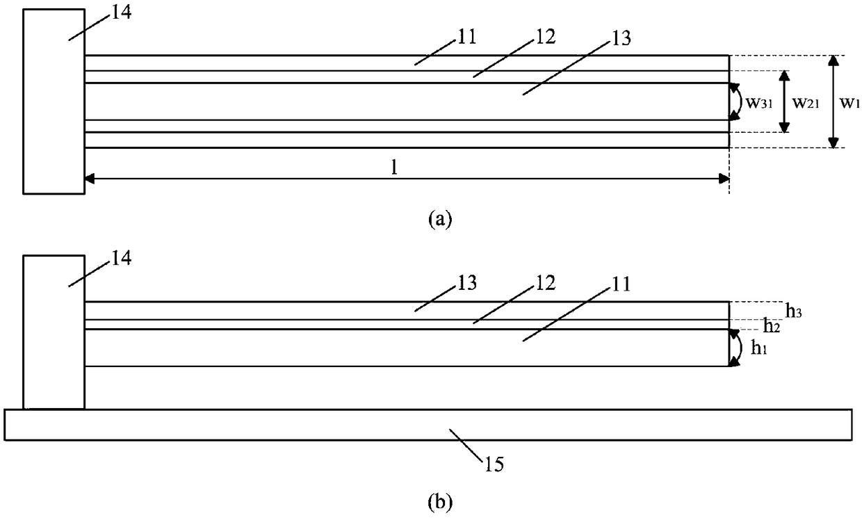
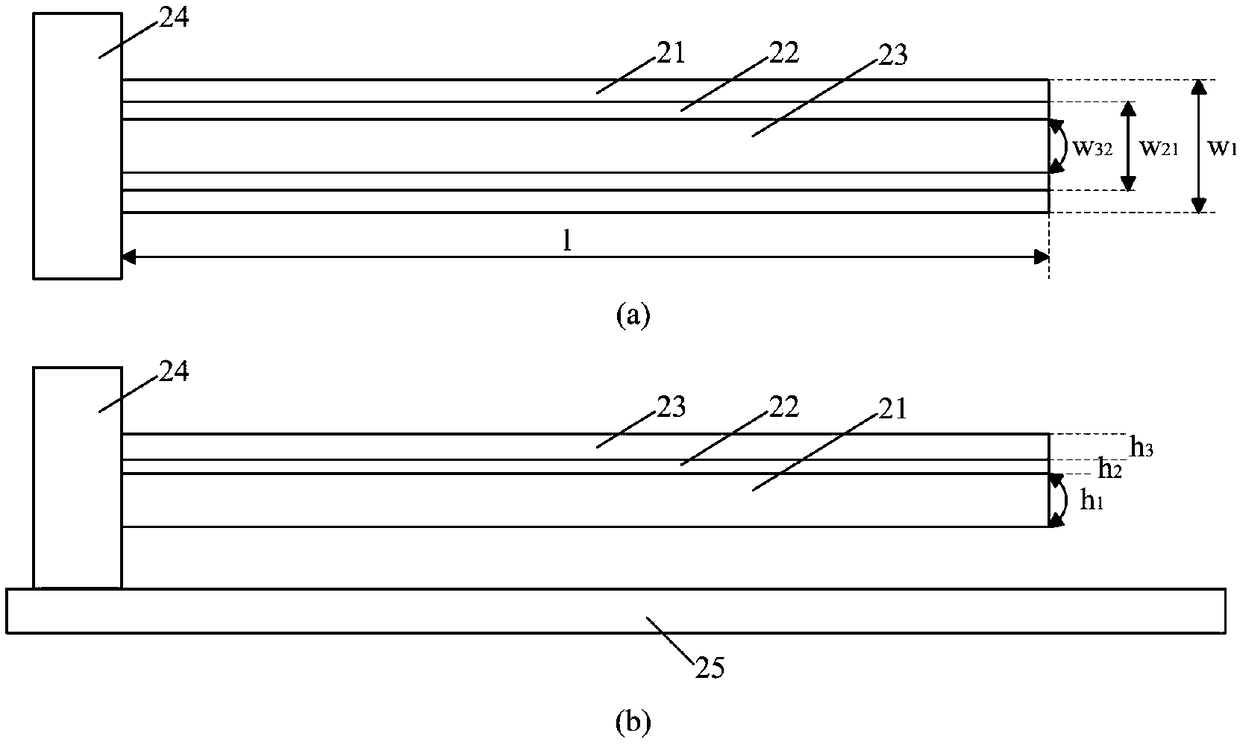
[0026] figure 2 is a structural schematic diagram of the first three-layer cantilever beam 201, wherein figure 2 (a) is a plan view, figure 2 (b) is a side view. The first three-layer cantilever beam 201 includes: a bottom layer 11 , a middle layer 12 , a top layer 13 , an anchor region 14 and a substrate 15 . The anchor region 14 is fixed on the substrate 15, and other regions except the anchor region 14 are suspended to form a cantilever beam structure. The bottom layer 11 is a polysilicon layer, the middle layer 12 is a piezoelectric film material layer, and the top layer 13 is a metal layer. The length of the first three-layer cantilever beam 201 is l. The thickness of the bottom layer 11 of the first three-layer cantilever beam 201 is h 1 , the width is w 1 ; The thickness of the middle layer 12 of the first three-layer cantilever beam 201 is h 2 , the width is w 21 ; The thickness of the top layer 13 of the first three-layer cantilever beam 201 is h 3 , the w...

specific Embodiment 2

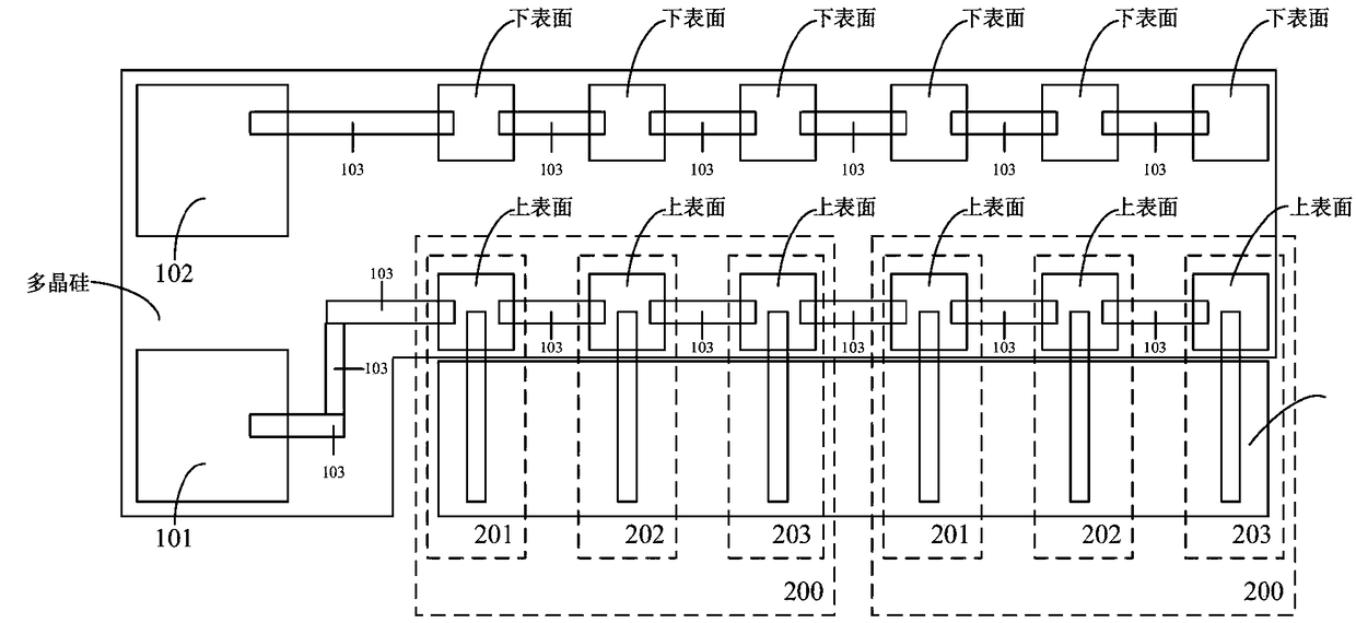
[0032] A kind of three-layer cantilever beam constituting the test model 200 is manufactured by basic micro-electromechanical processing technology, and the specific steps are as follows:

[0033] step 1:

[0034] A layer of oxide layer is grown on a 400 μm silicon substrate, and a layer of polysilicon bottom layer is grown on it, and a layer of photoresist PSG is deposited; it is annealed in an environment filled with argon and kept at 1050°C for 1 hour, The polysilicon is doped; the PSG is then wet etched away.

[0035] Step 2:

[0036] A 0.2μm oxide layer is grown, and a positive photoresist is spin-coated on it, and the pattern of the first mask plate PADOXIDE is copied onto the photoresist; the exposed part of the photoresist is removed and wet-etched Etch away unwanted oxide layers.

[0037] Step 3:

[0038] Reactive sputtering method (Reactive Sputtering) is used to sputter the intermediate piezoelectric material AlN; spin-coat positive photoresist on it, and the pa...

specific Embodiment 3

[0047] Using the test model 200 and the instrument, the Young's modulus of each layer material of the cantilever beam is extracted by the resonance frequency method. The step of extracting Young's modulus includes: using an instrument to measure the first-order resonance frequency, and obtaining the Young's modulus through analytical calculation.

[0048] Step 101: Use an instrument to measure the first-order resonance frequency, including: measuring the first-order resonance frequency f of the first three-layer cantilever beam 201 1 , measuring the first-order resonant frequency f of the second and third layer cantilever beams 202 2 and measure the first-order resonant frequency f of the third three-layer cantilever beam 203 3 ,details as follows:

[0049] Step 101-1: Use a digital holographic microscope (DHM-R2200, Lyncée Tec SA, Switzerland) to determine whether the first three-layer cantilever 201, the second three-layer cantilever 202, and the third three-layer cantilev...


PUM


Abstract

The invention relates to the technical field of material parameter on-line testing for a micro electromechanical system, and provides a film material lateral piezoelectric coefficient testing model based on a multi-layer cantilever beam and a method thereof. The testing model consists of three cantilever beams which have nonlinear correlation between middle layer and top layer width combination, wherein the materials, the thicknesses, and the lengths of the bottom layer, the middle layer, and the top layer of the three cantilever beams are exactly the same. The testing method comprises the steps of: firstly measuring the first-order resonance frequency of each cantilever beam; extracting the Young modulus of each layer of material of each cantilever beam based on a resonant frequency method; measuring the tip displacement of any one cantilever beam based on an inverse piezoelectric effect method; and finally, analyzing to obtain the transverse piezoelectric coefficient d31 of the filmmaterial used in the middle layer of the cantilever beams based on an energy method. According to the film material lateral piezoelectric coefficient testing model based on the multi-layer cantileverbeam and the method thereof, the testing model is simple; the machining process can be synchronous with the MEMS; no special machining requirements are needed; the testing method is low in solution complexity, small in calculation amount, and easy to operate; the testing process has repeatability, stability, and high efficiency; and the method meets online testing requirements.

Description

technical field [0001] The invention relates to the technical field of on-line testing of micro-electromechanical system material parameters, in particular to a testing model and method for transverse piezoelectric coefficients of film materials based on multilayer cantilever beams. Background technique [0002] With the continuous progress and perfection of Micro-Electro-Mechanical System (MEMS, Micro-Electro-Mechanical System) technology, more and more micro-mechanical structures can be designed and manufactured. Most movable micromechanical structures are small in size and require the use of large amounts of thin-film materials. However, the mechanical properties of thin film materials cannot be measured by the mechanical parameters of macroscopic mechanical materials. Moreover, thin film materials, especially crystal materials, when forming structures such as thin films and thin beams, due to different processing techniques, even the same material often exhibits signifi...

Claims


Application Information

Patent Timeline
Patent Type & Authority Applications(China)
IPC IPC(8): G01R29/22
CPCG01R29/22
Inventor 张滕远周再发黄庆安
Owner SOUTHEAST UNIV
Learn More