
A kind of using method of preparing hydrogen fluoride circulating fluidized bed degassing device

A circulating fluidized bed and degassing device technology, applied in the direction of hydrogen fluoride, fluorine/hydrogen fluoride, etc., can solve the problems of specific surface area gas film mass transfer coefficient, gas phase flow pressure reduction, short liquid residence time, large gas phase pressure drop, etc. , to achieve the effect of improving thermodynamic efficiency, large liquid film mass transfer coefficient, and small liquid backmixing

Active Publication Date: 2020-03-10
东营睿港管道工程有限责任公司
View PDF7 Cites 0 Cited by
  • Summary
  • Abstract
  • Description
  • Claims
  • Application Information

AI Technical Summary

Problems solved by technology

[0003] The technical solutions proposed by prior art 1 and prior art 2 are degassing towers. The current degassing towers are generally plate towers or packed towers using structured packing. Packed towers are selected as degassing process devices, which are suitable for rapid and instantaneous reactions. The process has the advantages of high specific surface area, high gas film mass transfer coefficient, and reduced gas phase flow pressure. The disadvantage is that the liquid storage volume is small and the liquid stays in the packed tower for a short time; the plate tower is selected as the rectification process device, which is suitable for In the fast and medium speed reaction process, it has the advantages of small liquid backmixing, uniform residence time, and large liquid film mass transfer coefficient. The disadvantages are complex structure, large gas phase pressure drop, and low corrosion resistance of tower internals.
In summary, due to the limitation of the liquid storage capacity of the packed tower and the plate tower, the processing capacity is small, the mass transfer efficiency is low, the pressure drop is large, and the operating flexibility is small

Method used


Image

  • A kind of using method of preparing hydrogen fluoride circulating fluidized bed degassing device
  • A kind of using method of preparing hydrogen fluoride circulating fluidized bed degassing device
  • A kind of using method of preparing hydrogen fluoride circulating fluidized bed degassing device

Examples


Embodiment Construction

[0019] The present invention will be further described below in conjunction with the accompanying drawings and specific embodiments.

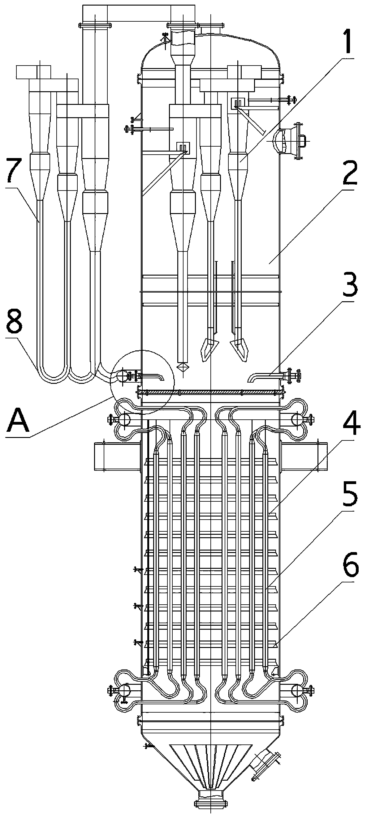
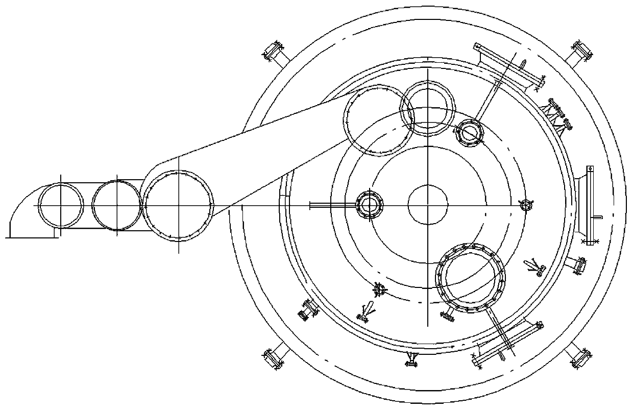
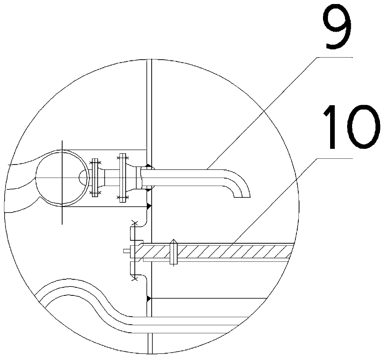
[0020] Such as figure 1 , figure 2 , image 3 Shown, a kind of using method of preparing hydrogen fluoride circulating fluidized bed degassing device is characterized in that:

[0021] Step 1. Before use, the liquid level of the U-shaped liquid sealer 8 at the bottom of the multi-stage cyclone separation condenser II7 must be observed through the liquid level gauge to ensure that the liquid level is at least 300mm higher than the feeder 9, and that the U-shaped liquid sealer 8 is in the normal working condition.

[0022] Step 2, remove heavy component H after rectification 2 SO 4 、H 2 After O, the hydrogen fluoride liquid enters from the feed liquid connecting pipe 3 designed in the middle of the circulating fluidized bed degassing tower body 2, and injects into the liquid receiving plate 10 at an injection temperature of 19.5±0.5°C. The...


PUM


Abstract

The invention relates to the technical field of fluorine industry, in particular to an application method of a circulating fluidized bed degasser for preparation of hydrogen fluoride. The applicationmethod is characterized in that a hydrogen fluoride liquid with heavy components H2SO4 and H2O removed through rectification enters the device through a feed liquid pipe designed at the central part of a circulating fluidized bed degassing tower and is injected into a liquid receiving tray; when the hydrogen fluoride liquid flows down to a primary fin plate, volatile components SO2, SiF4, CO2 andH2S are vaporized to form rising steam; and the purity of the non-volatile hydrogen fluoride liquid which is condensed by a multi-stage cyclone separation condenser and enriched at the bottom of the tower is continuously increased, thus achieving the purpose of removing light components.

Description

technical field [0001] The invention relates to the technical field of fluorine chemical industry, in particular to a method for using a circulating fluidized bed degasser for preparing hydrogen fluoride. Background technique [0002] Hydrogen fluoride has been widely used in electronics, chemical industry, petroleum and other industries. It is mainly used to produce fluorine salts, fluorohaloalkanes, fluorine refrigerants, corrode glass, impregnate wood, and electrolyze elemental fluorine. The degassing device is used to produce anhydrous One of the key equipment of hydrogen fluoride. Chinese invention patent (patent No. CN 201720751304.0, patent name is a degassing tower for the production of anhydrous hydrogen fluoride) discloses a degassing tower for the production of anhydrous hydrogen fluoride, which is characterized in that it includes a tower body, the Both sides of the bottom of the tower body cavity are connected with support rods, the top of the support rods is c...

Claims


Application Information

Patent Timeline
Patent Type & Authority Patents(China)
IPC IPC(8): C01B7/19
CPCC01B7/196
Inventor 杨松
Owner 东营睿港管道工程有限责任公司
Learn More