

Continuous vacuum electron beam coating method
A technology of vacuum electron beam and electron beam furnace, applied in vacuum evaporation plating, ion implantation plating, sputtering plating, etc., can solve problems such as difficult optimization and transformation, and achieve low cost, large coating thickness, and fast speed Effect
- Summary
- Abstract
- Description
- Claims
- Application Information
AI Technical Summary
Problems solved by technology
Method used
Image

Examples
Embodiment 1
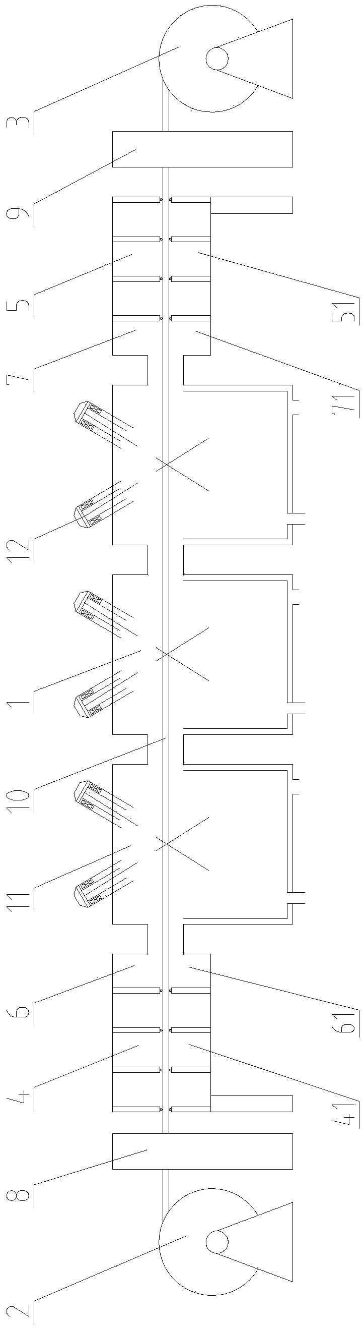
[0049] In the vacuum electron beam continuous coating device of the present embodiment:
[0050] An uncoiler and a rewinder are arranged in front of and behind the vacuum electron beam continuous coating device;
[0051] The electron beam furnace contains a working chamber, and the working chamber is equipped with an electron gun;
[0052] A vacuum chamber is placed in front of the vacuum electron beam continuous coating device, and a flat-plate vacuum heating device is installed in the vacuum chamber for single-stage heating;
[0053] Three vacuum chambers are placed in front of the working chamber in the vacuum electron beam coating device, and each vacuum chamber is equipped with a flat vacuum device for multi-stage vacuum;
[0054] Three vacuum chambers are installed behind the vacuum electron beam continuous coating device, and each vacuum chamber is equipped with a flat vacuum cooling device for multi-stage cooling;
[0055] The method for vacuum electron beam coating ...
Embodiment 2
[0058] In the vacuum electron beam continuous coating device of the present embodiment:
[0059] An uncoiler and a rewinder are arranged in front of and behind the vacuum electron beam continuous coating device;
[0060] The electron beam furnace contains 2 working chambers, and each working chamber is equipped with 2 electron guns;
[0061] A vacuum chamber is placed in front of the vacuum electron beam continuous coating device, and the vacuum chamber is equipped with a flat-plate vacuum heating device for single-stage heating;
[0062] 5 vacuum chambers are placed in front of the working chamber in the vacuum electron beam coating device, and each vacuum chamber is equipped with a flat vacuum device for multi-stage vacuum;
[0063] Two vacuum chambers are installed behind the vacuum electron beam continuous coating device, and each vacuum chamber is equipped with a flat vacuum cooling device for multi-stage cooling;
[0064] The method for vacuum electron beam coating of ...
Embodiment 3
[0067] In the vacuum electron beam continuous coating device of the present embodiment:
[0068] An uncoiler and a rewinder are arranged before and after the vacuum electron beam continuous coating device;
[0069] The electron beam furnace contains 3 working chambers, and each working chamber is equipped with 2 electron guns;
[0070] There are three vacuum chambers in front of the vacuum electron beam continuous coating device, and each vacuum chamber is equipped with a flat-plate vacuum heating device for multi-stage heating;
[0071] Six more vacuum chambers are placed in front of the working chamber in the vacuum electron beam coating device, and each vacuum chamber is equipped with a flat vacuum device for multi-stage vacuum;
[0072] Three vacuum chambers are installed behind the vacuum electron beam continuous coating device, and each vacuum chamber is equipped with a flat vacuum water cooling device for multi-stage cooling;
[0073] The method for vacuum electron be...
PUM
| Property | Measurement | Unit |
|---|---|---|
| width | aaaaa | aaaaa |
| thickness | aaaaa | aaaaa |
| thickness | aaaaa | aaaaa |
Abstract
Description
Claims
Application Information