
Air conditioner refrigeration defrosting equipment and condensate water treatment device

An air-conditioning refrigeration and processing device technology, applied in refrigerators, refrigeration components, refrigeration and liquefaction, etc., can solve the problems of unclean defrosting, unstable indoor temperature, and frequent defrosting, so as to reduce the emission of odor and avoid The effect of material precipitation enrichment and reduction of occupational health injuries

Inactive Publication Date: 2019-02-01
谢昶意
View PDF4 Cites 0 Cited by
  • Summary
  • Abstract
  • Description
  • Claims
  • Application Information

AI Technical Summary

Problems solved by technology

But our existing defrosting method will stop the compressor, then switch the four-way valve to switch to cooling operation, and at the same time, the indoor fan will stop running, which will cause the indoor temperature to be unstable.
[0003] In addition, due to the defrosting procedure of some air conditioners, the defrosting will not be clean. In this case, it is easy to defrost frequently, and the indoor temperature changes greatly, which makes people feel uncomfortable.
[0004] Moreover, the condensed water released by some air conditioners now basically flows out, and will not be recycled again, resulting in a waste of water resources

Method used


Image

  • Air conditioner refrigeration defrosting equipment and condensate water treatment device
  • Air conditioner refrigeration defrosting equipment and condensate water treatment device
  • Air conditioner refrigeration defrosting equipment and condensate water treatment device

Examples


Embodiment Construction

[0028] The technical solutions in the embodiments of the present invention will be clearly and completely described below in conjunction with the accompanying drawings in the embodiments of the present invention. Obviously, the described embodiments are only some of the embodiments of the present invention, not all of them. Based on The embodiments of the present invention and all other embodiments obtained by persons of ordinary skill in the art without making creative efforts belong to the protection scope of the present invention.

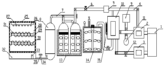
[0029] Such as Figure 1-5 As shown, the present invention provides an air-conditioning refrigeration defrosting equipment and a condensed water treatment device, including a power supply 1, a gas phase detector 2, a water quality detector 3, a first circulating water pipe 4, an organic waste water tank 8, a solid oxidant 9, an ozone oxidation System 10, liquid oxidant 11, crystallizer 13, reaction tank 14 and ultraviolet lamp oxidation system 1...


PUM


Abstract

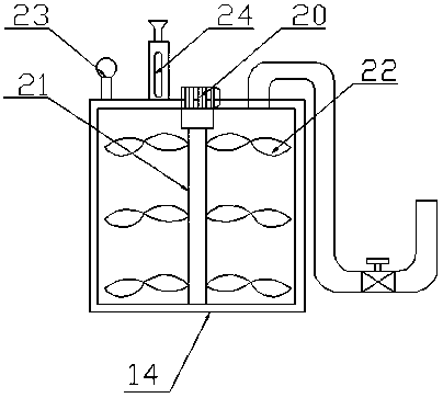
The invention discloses air conditioner refrigeration defrosting equipment and a condensate water treatment device. A power source, a gaseous phase detector, a water quality detector, a first circulation water pipe, an organic wastewater tank, a solid oxidant, an ozonation system, a liquid oxidant, a crystallizer, a reaction tank and an ultraviolet lamp oxidation system. The power source is electrically connected with the gaseous phase detector and the water quality detector. The gaseous phase detector is connected with the crystallizer and the ozonation system through the first circulation water pipe, and the upper end of the crystallizer is provided with a connecting pipe connected with the organic wastewater tank fixedly in a penetrating mode. A high temperature crystallizer and a low temperature crystallizer are arranged in the crystallizer and are each internally provided with a stirring shaft, wherein a plurality of stirring blades are fixedly arranged on the stirring shaft, andthe upper portion of the stirring shaft is provided with a strainer. Traditional multiple-effect evaporation is designed into the crystallizer and a heterogeneous catalysis oxidation system, electricenergy is the only operating cost, catalysis treatment of organic wastewater is conducted effectively in an environmentally friendly mode, and the actual demand of incessant and continuous treatment of the organic wastewater is achieved.

Description

technical field [0001] The invention relates to the technical field of air-conditioning refrigeration sewage treatment, in particular to an air-conditioning refrigeration defrosting equipment and a condensed water treatment device. Background technique [0002] In winter or when the external ambient temperature is low or the humidity is high, since the evaporation temperature of the air conditioner is lower than the outdoor temperature, it will condense into water in the condenser outside the air conditioner, and the low evaporation temperature will affect the heat transfer efficiency of the heat exchanger. The evaporation temperature is lower, and when it reaches below zero, frost or even ice will form on the outside. The current heat pump air conditioner has a defrosting function, that is, it runs cooling to defrost during the heating operation. Through the cooling operation, the outer heat exchanger is a condenser, and its condensation temperature is greater than zero, an...

Claims


Application Information

Patent Timeline
IPC IPC(8): F25B47/00
CPCF25B47/00F25B2347/00
Inventor 谢昶意
Owner 谢昶意
Learn More