
Air-spring-based semi-active control hydraulic suspension

A semi-active control and hydraulic suspension technology, applied in the direction of spring, spring/shock absorber, shock absorber-spring combination, etc., to achieve the effect of solving airtightness and realizing dynamic deformation

Active Publication Date: 2019-02-05
JILIN UNIV
View PDF5 Cites 4 Cited by
  • Summary
  • Abstract
  • Description
  • Claims
  • Application Information

AI Technical Summary

Problems solved by technology

Chinese patent CN 104154171 A discloses an air spring type semi-active control mount, but its disadvantage is that one side of the decoupling membrane is in contact with the liquid, and it cannot comprehensively feedback the extrusion of the liquid in the mount to the decoupling membrane. The motor controls the movement of the plug to realize the size of the opening of the air chamber. Whether it can ensure the airtightness inside the air chamber remains to be investigated.

Method used


Image

  • Air-spring-based semi-active control hydraulic suspension
  • Air-spring-based semi-active control hydraulic suspension
  • Air-spring-based semi-active control hydraulic suspension

Examples


Embodiment Construction

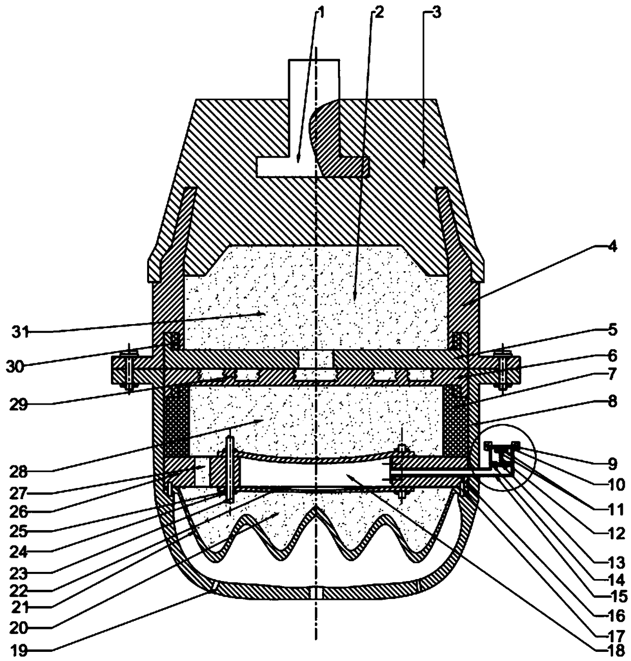
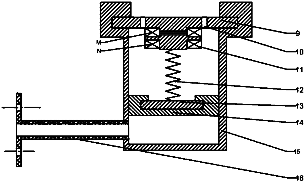
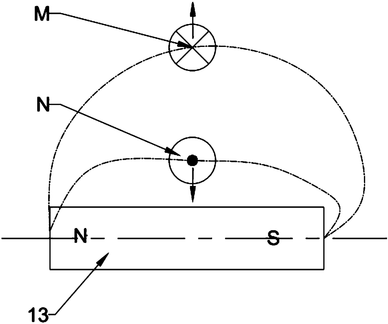
[0023] The actual idea of ​​vibration isolation provided by the present invention is: the liquid 2 inside the rubber main spring 3 deforms and squeezes the suspension from the upper liquid chamber 31 through the T-shaped inertial channel 29 to the middle liquid chamber 28 to squeeze the decoupling membrane 22, the decoupling membrane The air pressure of the cylindrical air chamber 18 inside 22 changes with the movement of the piston head 14 in the vertical direction, and the distance that the piston head 14 moves up and down can be controlled by controlling the current inside the solenoid 11 to control the solenoid 11 and the permanent magnet 13 Between the ampere force to precise control. When the decoupling film 22 needs greater rigidity, increase the energizing current in the electromagnetic coil 11 to increase the ampere force in the permanent magnet 13 and the electromagnetic coil 11 to realize the downward movement of the piston head 14 and increase the piston The pressur...


PUM


Abstract

The invention relates to an air-spring-based semi-active control hydraulic suspension. Through the air-spring-based semi-active control hydraulic suspension, the problem that the bandwidth of absorbable vibration frequency bands is small when an engine suspension absorbs external vibration is solved. The air-spring-based semi-active control hydraulic suspension achieves the effects of being capable of conducting full-band absorption on the absorbable vibration frequency bands from low frequency to high frequency, reducing vibration noise in a cab and improving the riding comfort. The air-spring-based semi-active control hydraulic suspension is composed of an upper suspension assembly, a lower suspension assembly and a cylindrical gas chamber. A suspension internal cavity is divided into anupper liquid chamber, a middle liquid chamber and a lower liquid chamber by an inertia channel and decoupling membranes. A T-shaped groove inertia channel can increase throttling loss and return lossof liquid flowing through the internal cavity and increase damping force. The cylindrical gas chamber formed by the two decoupling membranes communicates with an external piston. The direction and magnitude of current in an electromagnetic coil in the piston can be adjusted to realize up-down movement of the head of the piston, so that the pressure intensity of gas in the cylindrical gas chamberis adjusted, the rigidity of the decoupling membranes is dynamically adjusted, and the autokinetic degree of the suspension is dynamically changed finally. Accordingly, the purpose of full-band vibration absorption is achieved.

Description

Technical field [0001] The invention belongs to the technical field of automobile engine suspension, and in particular relates to a semi-active control hydraulic suspension based on an air spring. Background technique [0002] As consumers pay more and more attention to the subjective experience of car rides, good NVH performance has gradually become one of the core competitiveness of cars. However, as the power of the engine increases and the weight of the power system is lightened, the vibration excitation of the powertrain continues to intensify, which puts forward higher requirements for the performance of the automotive vibration isolation suspension system. At present, common suspension systems include rubber suspension, hydraulic suspension, semi-active control suspension and active suspension. Compared with the traditional passive suspension method, the semi-active control suspension can well attenuate the transmission of engine noise to the cabin. The semi-active contro...

Claims


Application Information

Patent Timeline
Patent Type & Authority Applications(China)
IPC IPC(8): F16F13/08
CPCF16F13/085
Inventor 陈志勇李松江逸飞陈龙
Owner JILIN UNIV
Learn More