
Display panel and display device

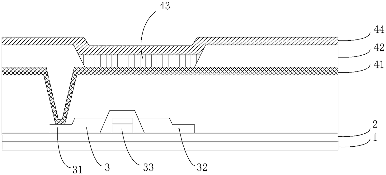
A technology of display panel and display area, applied in semiconductor devices, electrical components, circuits, etc., can solve problems such as the influence of display panel yield

Active Publication Date: 2019-02-05
KUNSHAN GO VISIONOX OPTO ELECTRONICS CO LTD
View PDF3 Cites 15 Cited by
  • Summary
  • Abstract
  • Description
  • Claims
  • Application Information

AI Technical Summary

Problems solved by technology

Therefore, the bonding yield has a great influence on the yield of the display panel

Method used


Image

  • Display panel and display device
  • Display panel and display device
  • Display panel and display device

Examples


Embodiment Construction

[0027] Reference will now be made in detail to the exemplary embodiments, examples of which are illustrated in the accompanying drawings. When the following description refers to the accompanying drawings, the same numerals in different drawings refer to the same or similar elements unless otherwise indicated. The implementations described in the following exemplary embodiments do not represent all implementations consistent with this application. Rather, they are merely examples of means consistent with aspects of the present application as recited in the appended claims.

[0028] The terminology used in this application is for the purpose of describing particular embodiments only, and is not intended to limit the application. Unless otherwise defined, the technical terms or scientific terms used in the present application shall have the common meanings understood by those skilled in the art to which the present invention belongs. "First", "second" and similar words used in...


PUM


Abstract

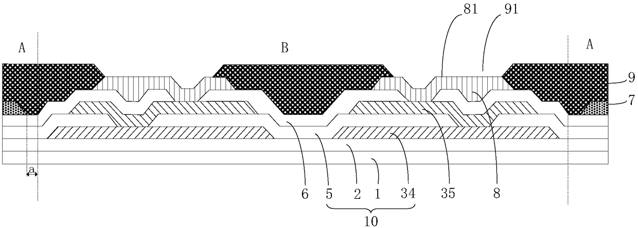
The invention provides a display panel and display device. The display panel includes a display area and a bonding area connected to the display area; the bonding area includes a substrate layer set,first metal layers formed on the substrate layer set, passivation layers formed on the first metal layers, second metal layers formed on the passivation layers, and protective layers formed on the second metal layers; the second metal layers are electrically connected to the first metal layers through the contact holes in the passivation layers; the protective layers have multiple through holes; and the parts of the second metal layers corresponding to the through holes are exposed to form multiple contact electrodes. Through the large area etching on first organic layers, third connection electrodes can have larger bare areas, and therefore, bonding areas can be enlarged, the number of ACF particles can be increased, bonding resistance can be reduced, and the yield rate of bonding can beimproved.

Description

technical field [0001] The present application relates to the display field, in particular to a display panel and a display device. Background technique [0002] Thin film transistors are widely used as pixel switching elements or driving circuit elements in various display devices, such as liquid crystal displays, organic light emitting diode displays, electronic paper displays, and the like. A pixel array of a display device is usually defined by multiple rows of gate lines and multiple columns of data lines interlaced with them. In the sub-pixel unit, the thin film transistor is used as a switching element, and under the control of the gate, an external data signal can be written into the pixel electrode in the sub-pixel unit through the thin film transistor to implement charging and discharging. [0003] Usually, the driving signal is provided by an integrated driving circuit (IC chip) bonded on the array substrate. Therefore, the bonding yield has a great influence on...

Claims


Application Information

Patent Timeline
IPC IPC(8): H01L27/12H01L27/32
CPCH01L27/124H10K59/131
Inventor 朱雪婧张金方朱晖
Owner KUNSHAN GO VISIONOX OPTO ELECTRONICS CO LTD
Learn More