Ferrite particles, resin composition and electromagnetic shielding material

A technology of resin composition and shielding material, applied in shielding materials, magnetic materials, iron compounds, etc., can solve the problem of inability to shield electromagnetic waves, etc.

Active Publication Date: 2019-02-05
POWDERTECH
View PDF6 Cites 5 Cited by
  • Summary
  • Abstract
  • Description
  • Claims
  • Application Information

AI Technical Summary

Problems solved by technology

Therefore, when the ferrite particles described in Patent Document 3 are used to form an electromagnetic wave shielding material, there is a problem that the electromagnetic wave shielding material cannot shield electromagnetic waves in the frequency band of 550 MHz to 1 GHz.

Method used


Image

  • Ferrite particles, resin composition and electromagnetic shielding material
  • Ferrite particles, resin composition and electromagnetic shielding material
  • Ferrite particles, resin composition and electromagnetic shielding material

Examples


preparation example Construction

[0060] As an example of the preparation method of ferrite raw material (granulated material), Fe raw material and Mn raw material, and if necessary, Mg raw material and Sr raw material are weighed to form the desired ferrite composition, and water is added to pulverize to prepare slurry material. The prepared slurry is granulated with a spray dryer, and then classified to prepare granules with a specified particle size. In consideration of the particle diameter of the obtained ferrite particles, the particle diameter of the granulated material is preferably 500 to 10000 nm. Furthermore, as another example, ferrite raw materials having a prepared composition are mixed and dry-milled, and after pulverizing and dispersing each raw material, the mixture is granulated and classified by a granulator to prepare granules with a predetermined particle diameter.

[0061] The thus-prepared granules were subjected to thermal spraying in the air to ferrite them. Thermal injection can use...

Embodiment 1

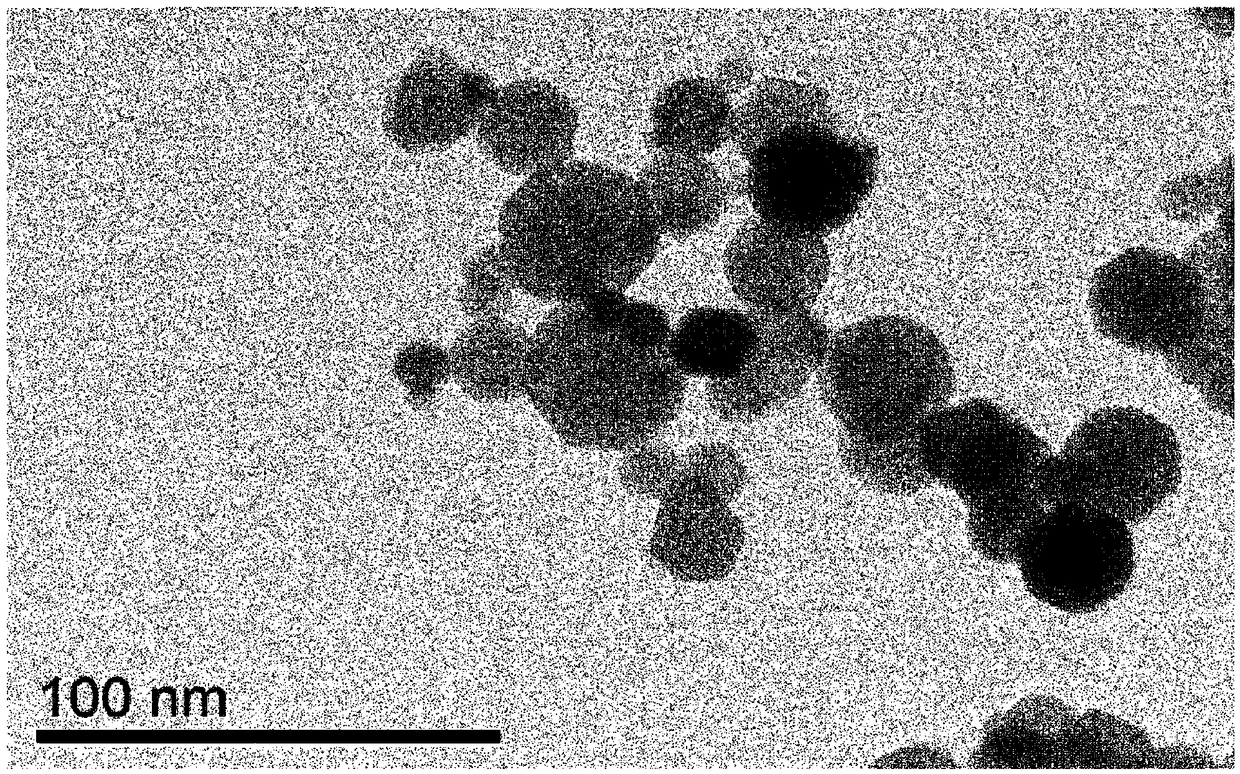
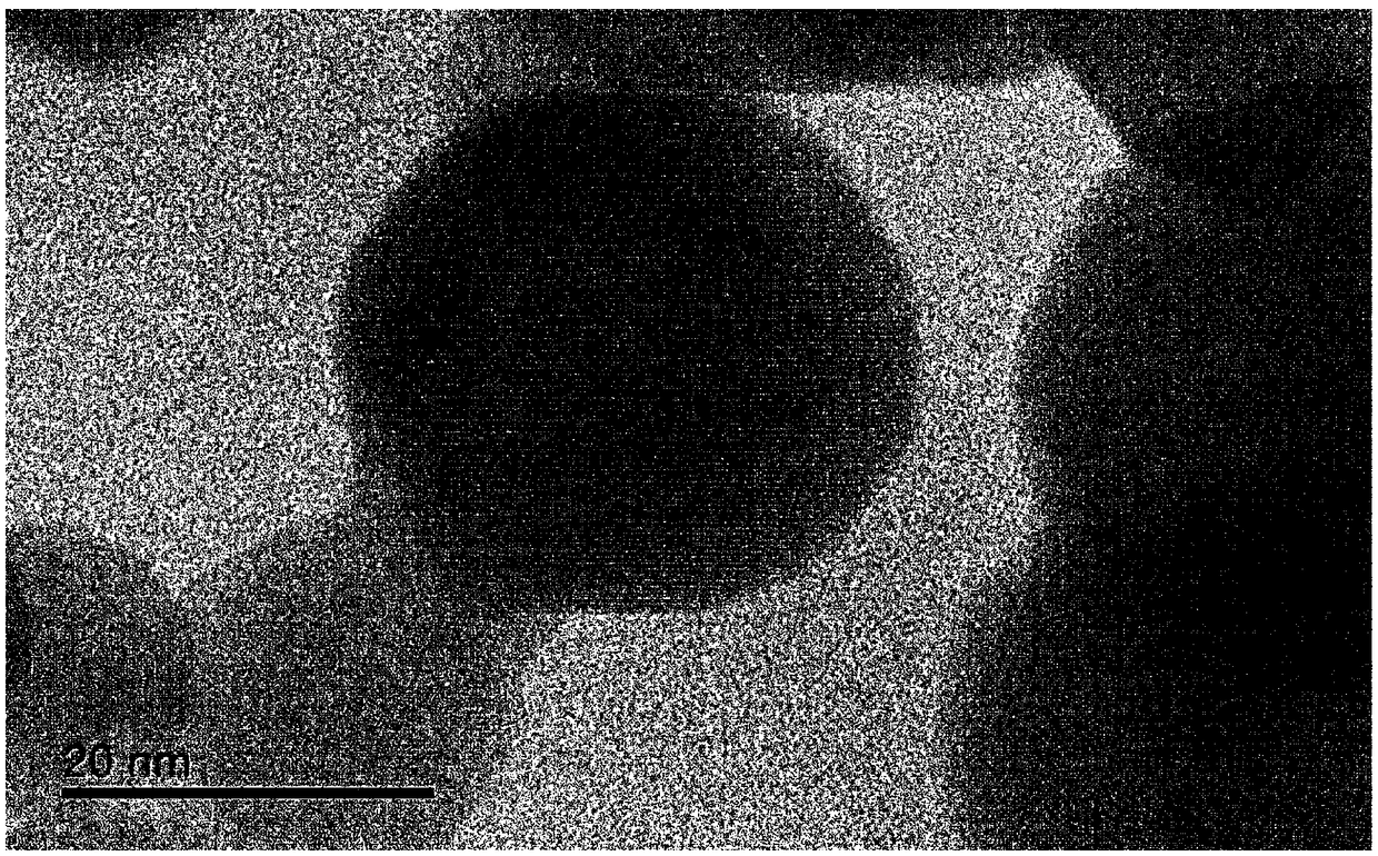
[0076] Measure and mix iron oxide (Fe 2 o 3 ) and manganese oxide (MnO). Water was added to the obtained mixture, and it was pulverized to prepare a slurry having a solid content of 50% by weight. The obtained slurry was granulated and classified with a spray dryer to prepare a granulated product with an average particle diameter of 5000 nm.

[0077] Subsequently, the obtained granules were dissolved in propane:oxygen=10Nm 3 / hr:35Nm 3 / hr in a combustible gas flame at a flow rate of about 40m / sec to perform ferriteization by thermal spraying, and then, carry on the airflow formed by the air supply and transport it to perform quenching in the atmosphere. At this time, since thermal spraying is performed while the granulated material is continuously flowing, the particles after thermal spraying and quenching are not mutually bonded but are independent from each other. Next, the cooled particles are collected by a filter provided on the downstream side of the air flow. At ...

Embodiment 2

[0079] In this example, ferrite particles were produced in the same manner as in Example 1 except that iron oxide and manganese oxide were in a molar ratio of 50:50.


PUM

PropertyMeasurementUnit
particle sizeaaaaaaaaaa
specific surface areaaaaaaaaaaa

Abstract

One purpose of the present invention is to provide ferrite particles which are capable of achieving high magnetic permeability in a frequency band of from 1 MHz to 1 GHz. Another purpose of the present invention is to provide: a resin composition which contains the ferrite particles; and an electromagnetic shielding material which is formed from this resin composition. Ferrite particles accordingto the present invention are single crystals having an average particle diameter of 1-2,000 nm, and have the shapes of spherical particles. The ferrite particles are characterized by substantially containing no Zn and by containing 3-25% by weight of Mn and 43-65% by weight of Fe. The ferrite particles are also characterized in that the real part u ' of the complex magnetic permeability as measured using a molded body that is formed from the ferrite particles and a binder resin has the maximum value in a frequency band of from 100 MHz to 1 GHz.

Description

technical field [0001] The present invention relates to ferrite particles, a resin composition containing the ferrite particles, and an electromagnetic wave shielding material composed of the resin composition. Background technique [0002] Conventionally, it is known that calcined ferrite particles are formed into a sintered body, which is further used as a magnetic core material, electromagnetic wave shielding material, etc. (for example, refer to Patent Document 1). [0003] As the electromagnetic wave shielding material using ferrite particles, a resin composition containing ferrite particles formed into a sheet shape may be used. By attaching a sheet-shaped electromagnetic wave shielding material to digital electronic equipment such as personal computers or mobile phones that need to shield electromagnetic waves, it is possible to prevent the leakage of electromagnetic waves to the outside of the electronic equipment, or the mutual interference of electromagnetic waves ...

Claims


Application Information

Patent Timeline
Patent Type & Authority Applications(China)
IPC IPC(8): H05K9/00C01G49/00C30B29/22H01F1/34
CPCC01G49/00C30B29/22H01F1/34H05K9/0075C01G49/0072C08K3/22H01F1/344H05K9/0081C08K2003/2275C01P2004/04C01P2004/32C01P2004/61C01P2004/62C01P2004/64C01P2006/42C08K7/18C08K2003/2265C08K2201/005C08K2201/01C08K2201/011C30B29/60H05K9/00
Inventor 小島隆志石井一隆杉浦隆男五十嵐哲也安賀康二
Owner POWDERTECH
Why Eureka
Try Eureka