System and method for eliminating white wake of flue gas

A flue gas and wake technology, which is applied in the field of systems for eliminating the white wake of the flue gas, can solve the problems of high operating costs, inconsistent with the development direction of energy saving and consumption reduction, and high consumption of electricity and heat, so as to reduce the contribution and eliminate the white wake. , the effect of reducing relative humidity

Inactive Publication Date: 2019-02-12
李俊峰 +1
View PDF3 Cites 4 Cited by
  • Summary
  • Abstract
  • Description
  • Claims
  • Application Information

AI Technical Summary

Problems solved by technology

In order to eliminate the white smoke trail, some people have invented a system that uses water from rivers and lakes to indirectly cool the flue gas through a heat exchanger or directly spray the flue gas without a heat exchanger, and some people have invented a system that uses steam to indirectly heat the flue gas through a heat exchanger. The system uses high-temperature flue gas to heat the flue gas direc...

Method used


Image

  • System and method for eliminating white wake of flue gas
  • System and method for eliminating white wake of flue gas
  • System and method for eliminating white wake of flue gas

Examples


Embodiment 1

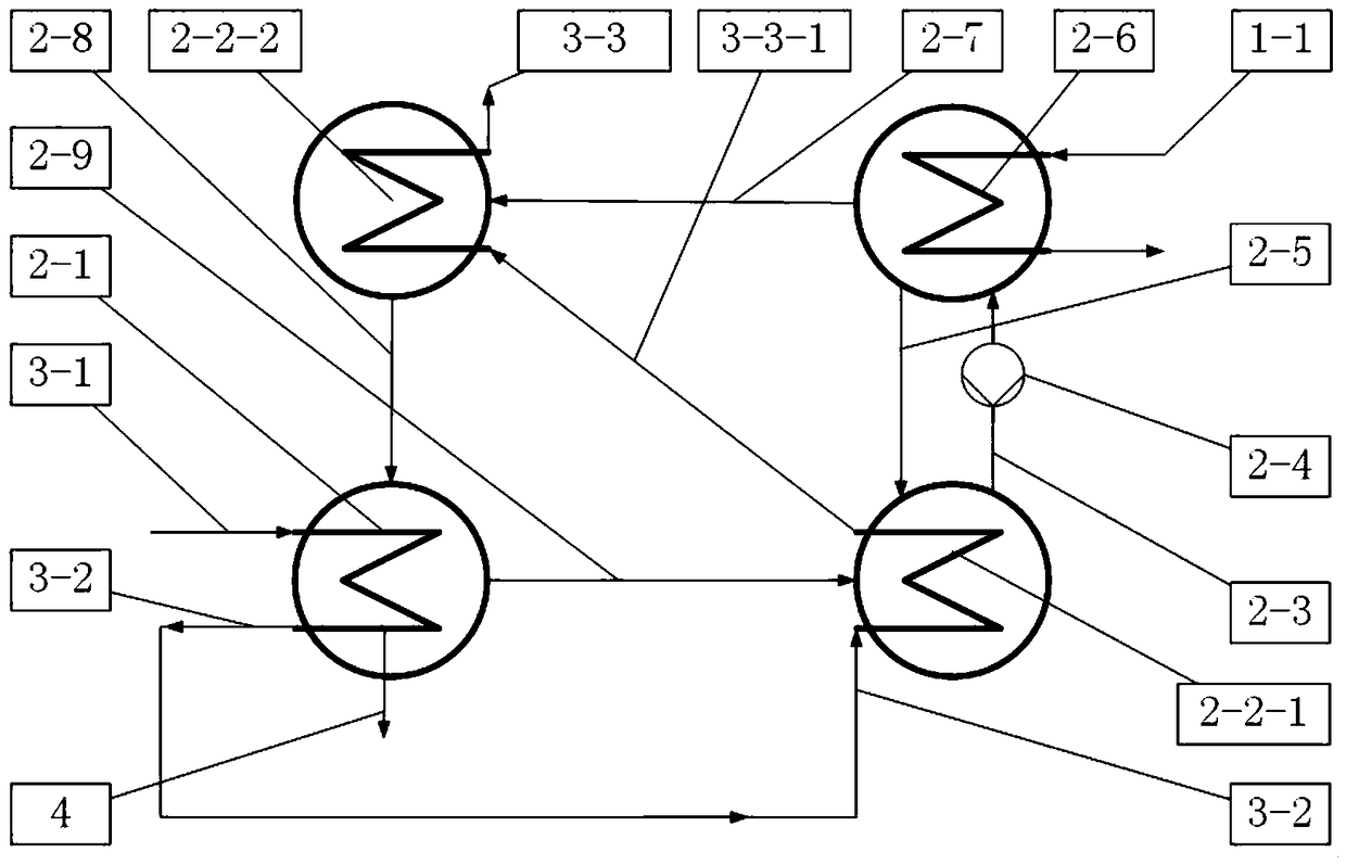
[0040] Such as figure 2 , using an absorption heat pump, the absorption heat pump driving energy is steam or high-temperature flue gas 1-1 to drive the heat pump 2 to work, when the heat pump 2 is working, the flue gas 3-1 to be treated enters the flue gas cooling unit 2-1 of the heat pump, Cooling and cooling, and the water in the flue gas condenses and precipitates, and the condensed water 4 is recovered by the condensed water recovery unit, which can be reused to save water resources. The amount of condensed water 4 is equal to the amount of water contained in the flue gas 3-1 to be treated minus the cooling The amount of water contained in the cooled flue gas 3-3, the water in the flue gas condenses in the process to take out the fine particle pollutants and soluble pollutants in the flue gas, so that the flue gas finally discharged into the atmosphere 3- 3 Cleaner and cleaner, the cooled flue gas 3-2 comes out of the flue gas cooling unit 2-1, then enters the flue gas he...

Embodiment 2

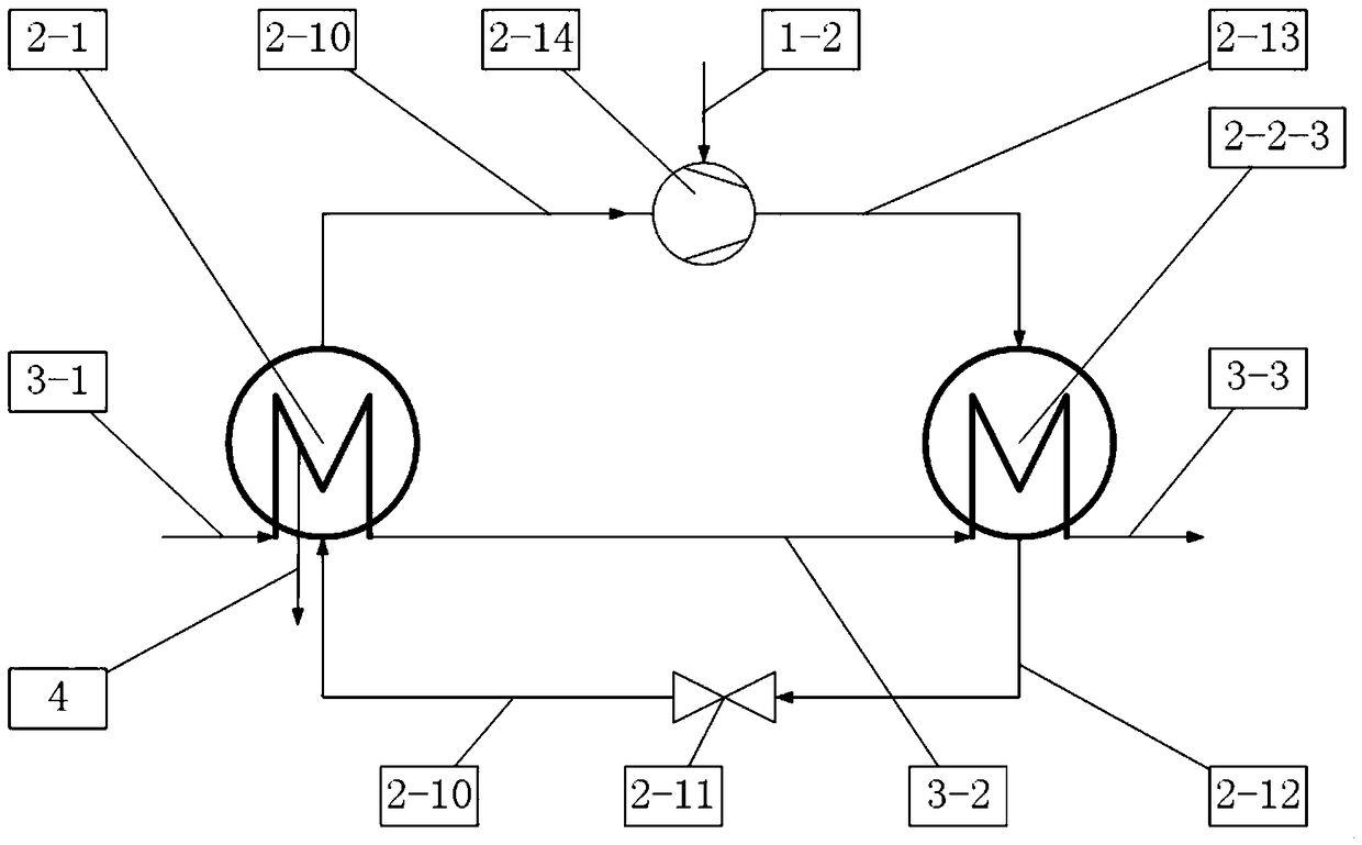
[0043] Such as image 3 , using a compressor heat pump to implement, the compression heat pump drives energy 1-2 to drive the compression heat pump compressor 2-14 to work, and drives the heat pump 2 to work. When the heat pump 2 is working, the compression heat pump gaseous expansion working medium 2-10 is The heat pump compresses 2-14 to become a compression heat pump high temperature and high pressure gaseous working medium 2-13. In the flue gas heating unit 2-2, the high temperature and high pressure working medium 2-13 passes through the compression heat pump condenser 2-2-3, The heat is transferred to the flue gas to be heated 3-2 to become a compression heat pump low-temperature high-pressure liquid working fluid 2-12, and the flue gas to be heated 3-2 absorbs the heat of the liquid high-temperature working fluid in the heat pump condenser 2-2-3 Heated into high-temperature flue gas 3-3, the heated flue gas 3-3 is discharged into the atmosphere without white smoke, and ...


PUM


Abstract

The invention provides a system and a method for eliminating white wake of flue gas. The system comprises energy source supply equipment, a heat pump and a chimney, wherein the energy source supply equipment is used for providing a drive energy source for the heat pump to work. The system has the advantages that by utilizing the characteristic of wet physical property of enthalpy in flue gas changing along with temperature, and utilizing the principle of the heat pump, a small amount of steam and power is consumed for driving the heat pump to circulate; the flue gas is cooled by the drive heatsource and the self heat of the flue gas to reduce the temperature of flue gas and dehumidify; then, the flue gas is heated to increase the temperature of the flue gas, the relative humidity of the flue gas is reduced, and the white wake of the flue gas is effectively eliminated; one part of water steam in the flue gas can be recycled and reutilized, and the fine particulate pollutants and soluble pollutants in the flue gas can be collected along with the condensate of flue gas, so that the flue gas which is exhausted into atmosphere is cleaner; the contribution degree of flue gas to the atmosphere haze pollution is greatly reduced.

Description

technical field [0001] The invention belongs to the technical field of energy saving and emission reduction, and in particular relates to a system and method for eliminating white trails of flue gas. Background technique [0002] The flue gas of coal-fired power plants is discharged into the atmosphere through the chimney. Due to reasons such as the background color of the sky, sky lighting, and viewing angles, etc., it is usually white, gray, blue, etc. visually, becoming a "colored plume". With continuous development, the current "colored plume" is mainly "white plume". [0003] Most of the desulfurization systems of coal-fired generating units in my country adopt the limestone-gypsum wet desulfurization process (hereinafter referred to as wet desulfurization), which can reduce the temperature of the flue gas to 45-55 ° C, and these low-temperature saturated wet flue gases enter the atmosphere directly through the chimney environment, when condensed, it condenses into tiny...

Claims


Application Information

Patent Timeline
IPC IPC(8): B01D53/26
CPCB01D53/26B01D53/265B01D2258/0283B01D2257/80
Inventor 李俊峰王凡
Owner 李俊峰
Why Eureka
Try Eureka