
Micro spot welding technology of nickel plated copper wiring harness and copper plate

A nickel-plated copper and wire harness technology, applied in welding equipment, manufacturing tools, resistance welding equipment, etc., can solve the problems of affecting welding quality, softening of copper material, and high melting temperature of nickel coating, so as to improve the quality of solder joints and reduce the The degree of bending deformation and the effect of improving the strength of solder joints

Inactive Publication Date: 2019-02-12
闫宇
View PDF8 Cites 2 Cited by
  • Summary
  • Abstract
  • Description
  • Claims
  • Application Information

AI Technical Summary

Problems solved by technology

The traditional single-shot micro-spot welding process for the micro-spot welding connection of the nickel-plated copper wire harness and the copper plate mainly has the following two problems: (1) the matching form of the wire harness and the board dissipates heat quickly, and the heat is difficult to concentrate; (2) the nickel coating melts The temperature is high, and the interface is difficult to melt to form an effective connection
If a large welding current is used to reach the melting point of the nickel coating, the copper will be softened due to excessive heat, resulting in large deformation, affecting the welding quality, and welding cracks and other process problems.
If a small welding current is used, it is difficult for the nickel coating to reach the melting temperature, resulting in process problems such as missing welding

Method used

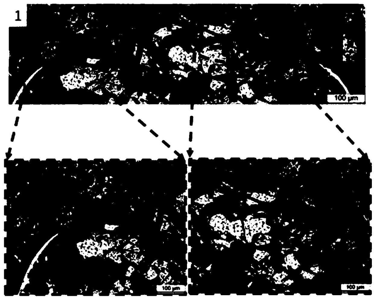
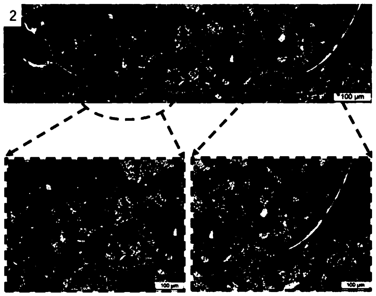

Image

  • Micro spot welding technology of nickel plated copper wiring harness and copper plate
  • Micro spot welding technology of nickel plated copper wiring harness and copper plate
  • Micro spot welding technology of nickel plated copper wiring harness and copper plate

Examples


Embodiment Construction

[0027] The present invention will be further described according to the drawings and embodiments below.

[0028] The micro-spot welding process of the nickel-plated copper wire harness and the copper plate includes the preloading of the welded parts, the first welding, the first cooling, the second welding, the second cooling, the third welding and the butt welding The specific operation steps of the whole welding are: first clamp the nickel-plated copper wire harness and copper plate to be welded together on the tooling, start the switch of the MIYACHI ISB-800A model spot welding machine, and the positioned workpiece to be welded will automatically run to Below the electrode, the welding head is lowered, and the workpiece to be welded enters the middle of the tungsten-copper electrode. The electrode will clamp the nickel-plated copper wire harness and the copper plate to be welded. The clamping force can be 150-180N. The clamping force of this embodiment is preferably 170N to ...


PUM


Abstract

The invention discloses a micro spot welding technology of a nickel plated copper wiring harness and a copper plate. The technological process of the micro spot welding technology sequentially comprises the steps of welding part pre-pressing, welding of the first time, cooling of the first time, welding of the second time, cooling of the second time, welding of the third time and pressure maintaining on a welding part. According to the micro spot welding technology, a nickel plated layer of a joint interface can be molten, and the influence of the residual nickel plated layer on the connectingquality of a welding joint is effectively reduced; under the work condition of welding of one time, mechanical embedment serves as the connecting manner of the nickel plated copper wiring harness andthe copper plate; by means of the work condition of welding of multiple times, solid phase connection between the nickel plated copper wiring harness and the copper plate can be achieved, and the connecting strength of the welding spot can be improved; and by means of the technological method of welding of multiple times, the bending and deforming degree of the copper plate can be effectively reduced, the technological problems of welding spot cracking and the like can be solved, and the connecting quality of the welding spot can be improved.

Description

technical field [0001] The invention belongs to the technical field of welding technology, and specifically designs a micro-spot welding technology of a nickel-plated copper wire harness and a copper plate. Background technique [0002] The rectifier diode is an important part of the motor driver, and its connection quality has an important impact on the service life of the driver. The matching form of nickel-plated copper wire harness and copper plate is a common connection form in rectifier diodes. The micro spot welding process is widely used in the field of micro-scale joining due to its advantages of high automation and low cost. The traditional single-shot micro-spot welding process for the micro-spot welding connection of the nickel-plated copper wire harness and the copper plate mainly has the following two problems: (1) the matching form of the wire harness and the board dissipates heat quickly, and the heat is difficult to concentrate; (2) the nickel coating melts...

Claims


Application Information

Patent Timeline
Patent Type & Authority Applications(China)
IPC IPC(8): B23K11/11B23K11/36
CPCB23K11/11B23K11/36
Inventor 闫宇
Owner 闫宇
Learn More