
Electroplating cathode hanging device

A hanger and cathode technology, applied in the electrolysis process, electrolysis components, current conduction devices, etc., can solve the problems of hanger main body damage, easy leakage, easy heat and burnt, etc., to prolong service life, improve coating quality, Guaranteed strength effect

Pending Publication Date: 2019-02-12
吉姆西半导体科技(无锡)有限公司
View PDF0 Cites 1 Cited by
  • Summary
  • Abstract
  • Description
  • Claims
  • Application Information

AI Technical Summary

Problems solved by technology

[0003] The electroplating hangers produced by the prior art have the following deficiencies: 1) the non-plated surface of the product is prone to seepage and the conductive area is easily plated with a coating; 2) the conductive contact part is in poor contact for a period of time, resulting in uneven coating of the product; 3) The current conduction part is easy to heat and burn, resulting in damage to the main body of the hanger

Method used


Image

  • Electroplating cathode hanging device
  • Electroplating cathode hanging device
  • Electroplating cathode hanging device

Examples


Embodiment Construction

[0028] The present invention will be described in further detail below in conjunction with examples and specific implementation methods.

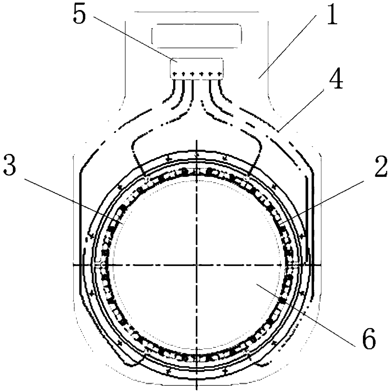
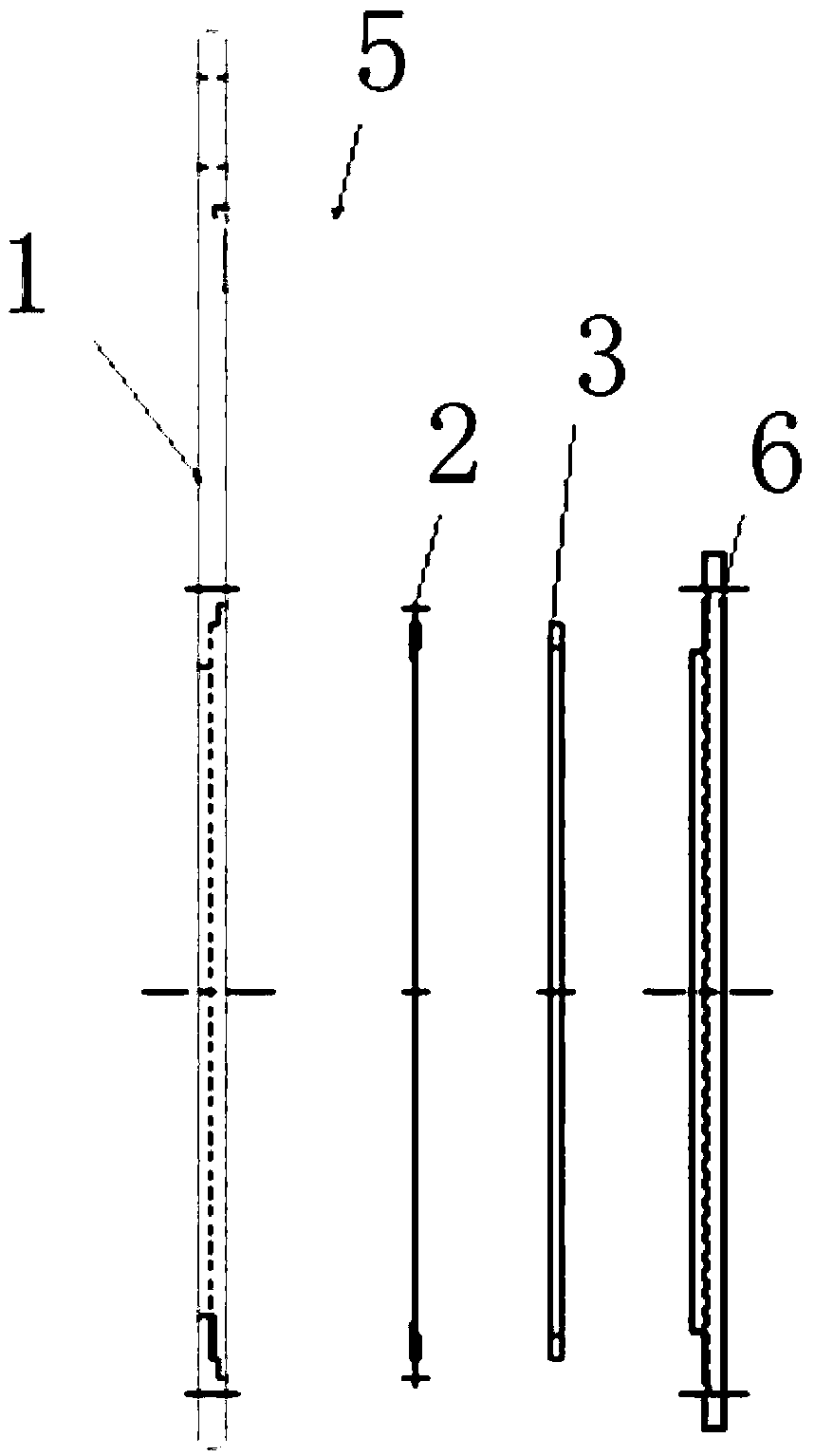
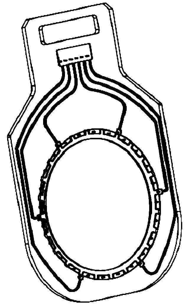
[0029] Such as Figure 1-7 As shown, the electroplating cathode hanger has a structure including a hanger main body 1, a conductive sheet 2, a pressing plate 3, a conductive thread 4, a conductive hook 5 and a rear cover 6, wherein the lower part of the hanger main body 1 is provided with a shape matching with the conductive sheet 2. Mounting groove, the conductive sheet 2 is pressed into the mounting groove on the main body of the hanger 1 through the pressure plate 3 and fixedly connected by A screws, the outer surface of the conductive sheet 2 is covered with fluororubber, the edge of the conductive sheet 2 is provided with bumps, and the main body of the hanger 1 The upper part is provided with a conductive hook 5, and the main body of the hanger 1 is provided with several grooves matching the shape of the conductive wire. The conductiv...


PUM

PropertyMeasurementUnit
thicknessaaaaaaaaaa
thicknessaaaaaaaaaa

Abstract

The invention provides an electroplating cathode hanging device. According to the structure of the hanging device, the lower portion of a hanging device main body is provided with an installing groovematched with an electricity conducting sheet in shape, the electricity conducting sheet is installed in an installing groove in the hanging device main body in a pressing manner through a pressing plate and fixedly connected through screws, the outer surface of the electricity conducting sheet is coated with fluororubber, a protruding block is arranged on the edge of the electricity conducting sheet, an electricity conducting hook is arranged on the upper portion of the hanging device main body, the hanging device main body is provided with a groove matched with an electricity conducting linein shape, the electricity conducting line is arranged in the groove in the hanging device main body and sealed and insulated through sealing rubber, one end of the electricity conducting line is connected with the electricity conducting hook, the other end of the electricity conducting line is connected with the electricity conducting sheet, and the rear cover plate covers the outer side face ofthe pressing plate and is fixedly connected with the hanging device main body through screws. The hanging device has the advantages that the hanging device main body is light and ensures strength; liquor is effectively prevented from entering the non-plated face of a product, and the situation that the electricity conducting sheet is plated with a plating layer, and the effect of the plating layeris influenced is avoided; the situation that the electricity conducting line is exposed in the liquor and burnt out possibly is avoided, and the service life is prolonged; and the electricity conducting hook enables currents to pass smoothly, and the quality of the plating layer is improved.

Description

technical field [0001] The invention relates to an electroplating cathode hanger, in particular to a hanger which fixes the cathode in the electroplating process and connects with the anode to conduct current to the product so as to form a certain plating layer. Background technique [0002] The function of the electroplating hanger is to hang or fix various products so that they are connected to the cathode. During anodizing and electropolishing, they are connected to the anode to conduct current to the product so as to form a plating layer (such as copper plating, nickel plating, gold plating, etc.) or other processing purposes. Specifically, the plated parts are transferred by the hanger, and loaded into the plating tank as a conductor, the plated parts are connected to the plating solution through the hanger, and after the current is connected, the current is passed into the plating solution from the electrode, so that Electrons near the parts are obtained, so that the ...

Claims


Application Information

Patent Timeline
Patent Type & Authority Applications(China)
IPC IPC(8): C25D17/00C25D17/08
CPCC25D17/004C25D17/007C25D17/08
Inventor 祁志明赵国安李松松孙永胜
Owner 吉姆西半导体科技(无锡)有限公司
Learn More