Combined revetment combined with near-term plan and long-term plan

A combined and combined technology, applied in the direction of pier, quay wall, embankment, etc., to achieve the effect of small dust problem, reduction of abandoned projects, and overall stability of bank revetment structure

Pending Publication Date: 2019-02-12
SHANGHAI MUNICIPAL ENG DESIGN INST GRP
View PDF0 Cites 6 Cited by
  • Summary
  • Abstract
  • Description
  • Claims
  • Application Information

AI Technical Summary

Problems solved by technology

[0003] The invention provides a combined revetment, which solves the situation that the implementation of landscape engineering along the river lags behind the embankment up-to-standard reconstruction project and the long-term planned blue line is inconsistent with the current river bank, and the land acquisition cannot be implemented according to the planned blue line in the near future. Long-term project planning to achieve simple, rapid and low-impact construction of the flood control wall in the near future. When the later stage can be implemented according to the blue line of the planned river and the hydrophilic requirements of the landscape are improved, the secondary retaining wall can be dismantled and reused to reduce abandoned projects. Reduce the difficulty of construction and reduce the impact of construction on the surrounding environment

Method used


Image

  • Combined revetment combined with near-term plan and long-term plan
  • Combined revetment combined with near-term plan and long-term plan
  • Combined revetment combined with near-term plan and long-term plan

Examples


Embodiment Construction

[0022] A preferred embodiment will be given below, and the present invention will be described more clearly and completely in conjunction with the accompanying drawings.

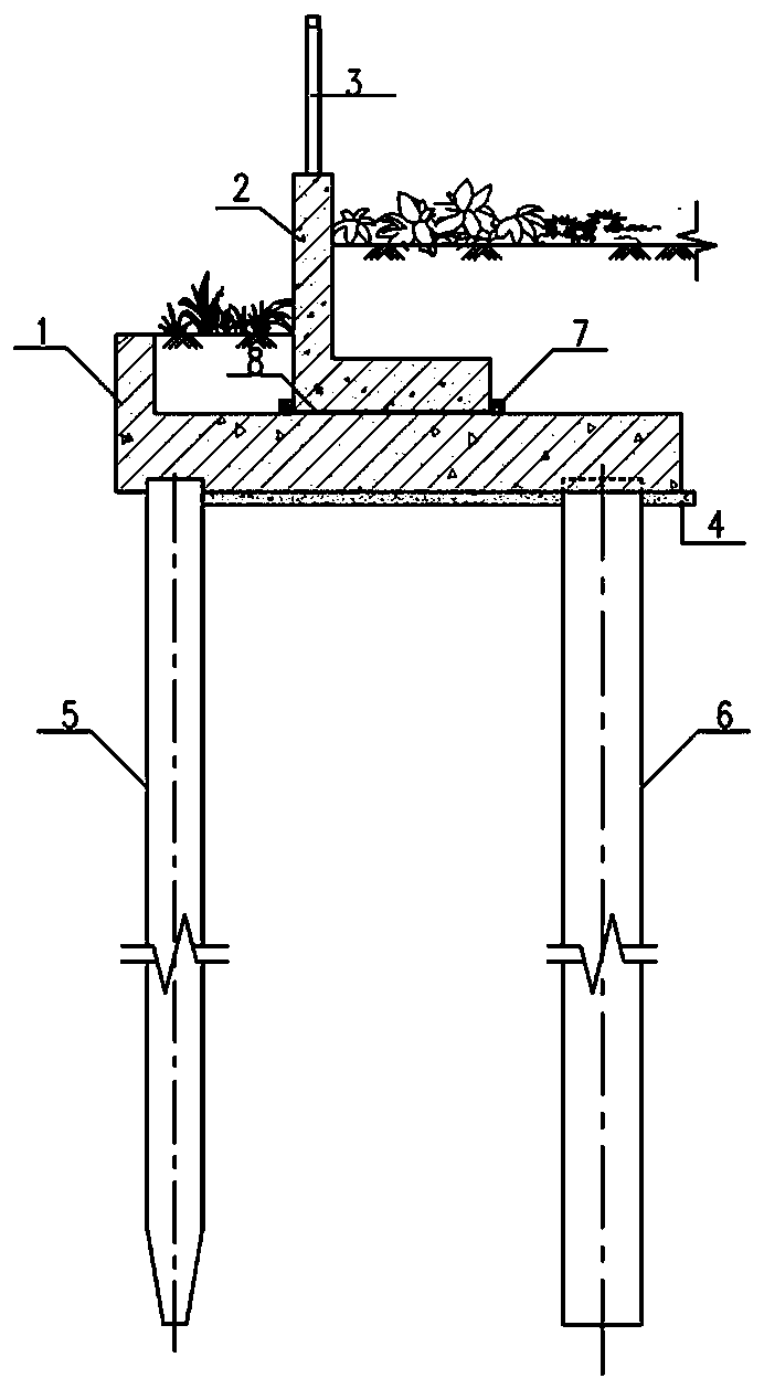
[0023] Such as figure 1 As shown, a combined revetment includes a primary revetment 1 and a prefabricated secondary L-shaped revetment 2. The prefabricated secondary L-shaped revetment 2 is cemented on the top of the primary revetment 1 through the mortar layer 8, and the bottom plate of the primary revetment is located on the plain concrete cushion 4 of C15. Pile foundations 5 and 6 are located below the primary bank revetment 1, and a C20 concrete block 7 is arranged on the upper surface of the primary bank revetment floor to assist the positioning of the secondary bank revetment during hoisting.

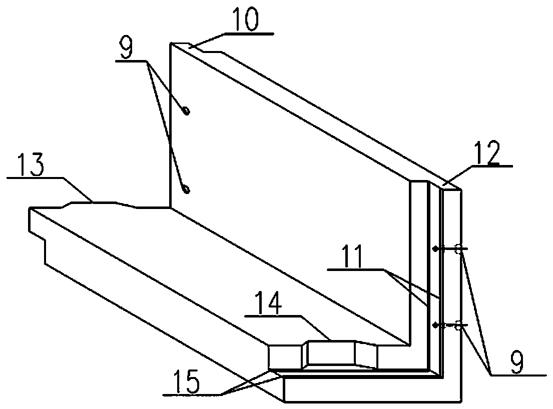
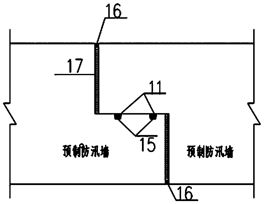
[0024] Such as figure 2 As shown, the prefabricated secondary L-shaped revetment 2 is spliced ​​by several prefabricated concrete revetment sections, which include bolts 7 in reserved holes, connecting convex...


PUM

PropertyMeasurementUnit
Thicknessaaaaaaaaaa
Thicknessaaaaaaaaaa
Lengthaaaaaaaaaa

Abstract

The invention discloses a combined revetment combined with a near-term plan and a long-term plan. The combined revetment comprises a primary revetment body and a prefabricated secondary L-shaped revetment body, the prefabricated secondary L-shaped revetment body is formed by splicing a plurality of concrete prefabricated revetment sections, the two ends of the concrete prefabricated revetment sections are correspondingly provided with connecting convex teeth and connecting concave teeth which cooperate with each other, every two adjacent concrete prefabricated revetment sections of the prefabricated secondary L-shaped revetment body are connected through the corresponding connecting convex tooth and connecting concave tooth, the connecting convex teeth and the connecting concave teeth areconnected through bolts, rubber water stopping grooves are formed between the connecting convex teeth and the connecting concave teeth, water swelling rubber strips are arranged in groove openings, the joints between the connecting convex teeth and the connecting concave teeth are filled with low-foaming polyethylene plates, and single-component polyurethane sealants are adopted for sealing on theperipheral surfaces of deformation joints. The combined revetment can be implemented according to a planned watercourse blue line in the later period, or when the hydrophilicity requirement for a landscape needs to be improved, the secondary revetment body can be disassembled and reused, so that waste engineering is reduced, the construction difficulty is reduced, and the influence of construction on the surrounding environment is reduced.

Description

technical field [0001] The invention relates to a combined bank revetment in consideration of short-term and long-term planning. Background technique [0002] At this stage, in addition to its own flood control and safety guarantee functions, revetment functions such as ecological landscape and hydrophilic requirements are also increasingly valued. In order to meet the hydrophilic needs of the landscape along the river, the form of secondary revetment is often used at present: the elevation of the top of the first revetment wall is lowered to improve the hydrophilic experience; the second revetment is arranged behind the first revetment wall combined with landscape functions, The height of the top of the wall meets the fortification requirements. However, due to various objective reasons, problems such as revetment construction process, landscape construction project, and adjustment of the blue line of the planned river cannot be implemented simultaneously. For the safety ...

Claims


Application Information

Patent Timeline
IPC IPC(8): E02B3/06E02B3/16
CPCE02B3/06E02B3/066E02B3/16
Inventor 李明兰士刚叶茂盛王建生董学刚石永超
Owner SHANGHAI MUNICIPAL ENG DESIGN INST GRP
Why Eureka
Try Eureka