
A grouting device for preventing and controlling water disasters in coal mines

A grouting device, disaster technology, applied in the direction of cement mixing device, clay preparation device, shaft equipment, etc., can solve the problems of large vibration, loud noise, power loss, etc.

Active Publication Date: 2020-07-07
HENAN POLYTECHNIC UNIV
View PDF7 Cites 0 Cited by
  • Summary
  • Abstract
  • Description
  • Claims
  • Application Information

AI Technical Summary

Problems solved by technology

[0004] The purpose of the present invention is to provide a kind of coal mine water disaster prevention grouting device, to solve the multiple motors proposed in the above-mentioned background technology is not only complicated, but also vibration is large, noise is large, power consumption is high, and inconvenient, one motor is easy to cause Excessive power loss will also lead to technical problems such as insufficient pump pressure and affect the grouting effect. It is inconvenient for the staff to push the trolley to power the stirring blade, so that the solidification of the grouting device during transportation cannot be prevented. Setting up a mixing tank makes it inconvenient for the staff to stir and mix the slurry they carry, which cannot avoid the occurrence of slurry bonding and solidification. At the same time, it is inconvenient for the staff to temporarily add additional adhesives or additives according to the cracking and leakage of the rock on site. Problems injecting into the rock surface after agitation mixing

Method used


Image

  • A grouting device for preventing and controlling water disasters in coal mines
  • A grouting device for preventing and controlling water disasters in coal mines
  • A grouting device for preventing and controlling water disasters in coal mines

Examples


Embodiment Construction

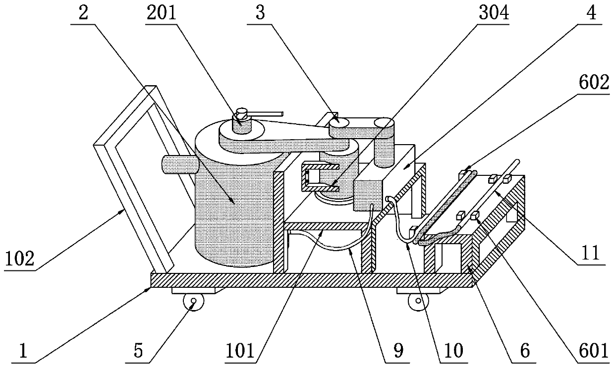
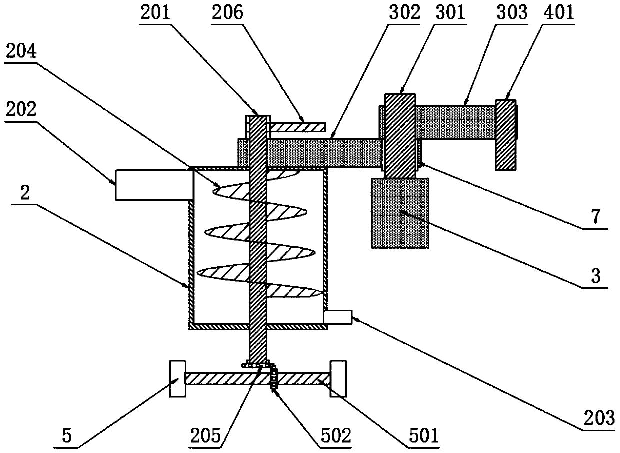
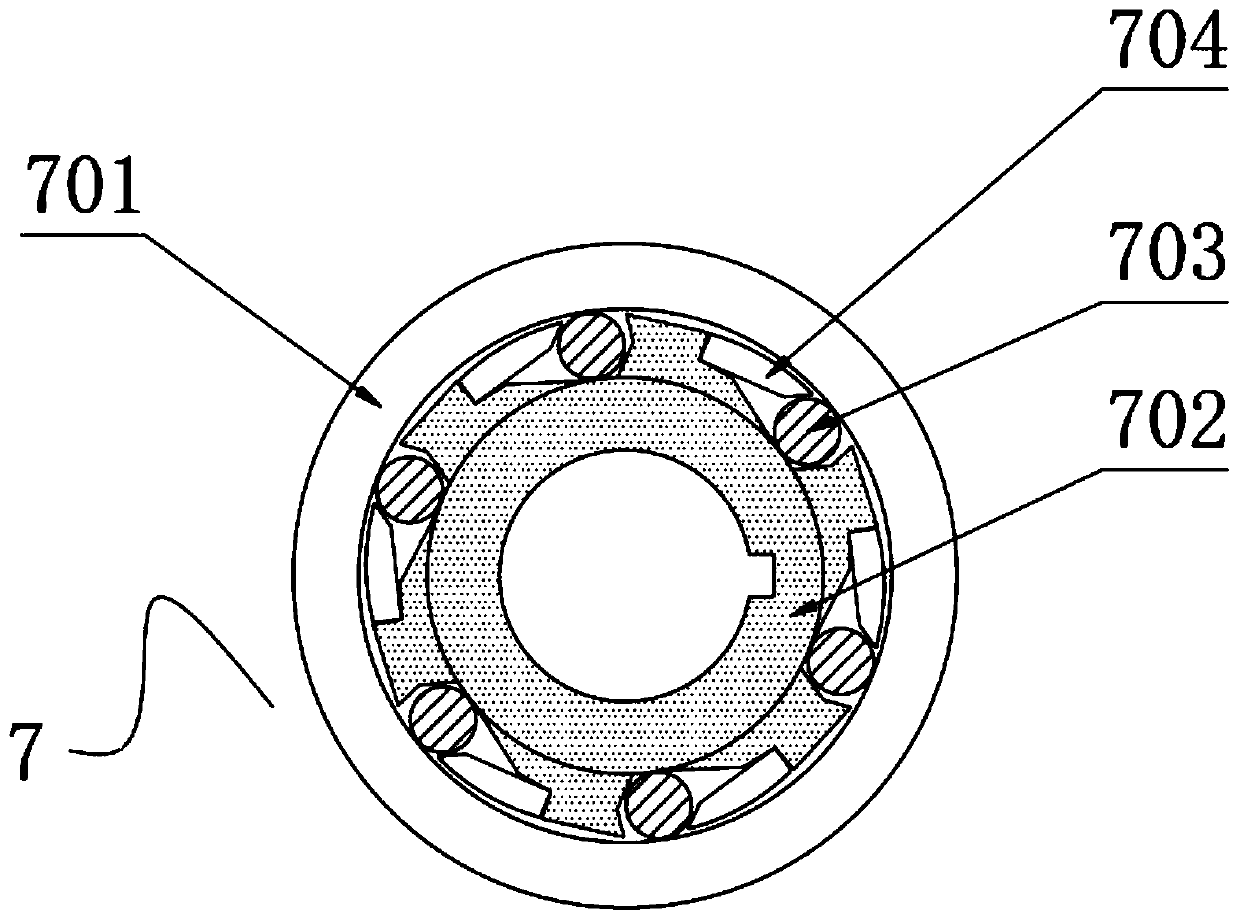
[0032] see Figure 1~4 , in an embodiment of the present invention, a coal mine water disaster prevention and control grouting device, including a bottom plate 1, a mixing tank 2, a motor 3, a hydraulic pump 4 and a grouting head assembly 11, the bottom of the bottom plate 1 is provided with a roller 5, the The first rotating shaft 201 extending vertically is arranged in the mixing barrel 2, and the stirring blade 204 is arranged on the first rotating shaft 201. It is characterized in that, the upper end of the first rotating shaft 201 protrudes from the mixing barrel 2, and The upper end of the first rotating shaft 201 and the output shaft of the electric motor 3 are connected by a transmission switch assembly, and the output shaft of the electric motor 3 is connected by transmission with the hydraulic pump 4, so as to drive the hydraulic pump to The grouting device provides power; the transmission switching assembly can make the motor 3 drive the first rotating shaft 201 in ...


PUM


Abstract

The invention discloses a grouting device for coal mine water disaster preventing and treating. According to the grouting device for coal mine water disaster preventing and treating, a motor can drivea first rotary shaft in a stirring barrel and a hydraulic pump to simultaneously rotate to work, and the motor can also be switched to only drive the hydraulic pump to rotate to work and not drive the first rotary shaft in the stirring barrel to rotate; switching of a transmission switching assembly is easy and convenient, switching of the transmission function is achieved only by switching the rotating direction of the motor, work of the motor can be effectively separated, the torque needing to be borne by the motor is lowered, mechanical consumption of the motor can be reduced, thus the purpose of energy saving can be achieved, and the motor can be protected against moving along with the grouting device in the process that the grouting device is pushed by a worker to move; and a grouting head assembly stretches into a to-be-grouted position, an oscillating assembly is arranged in the grouting head assembly and enables the grouting head assembly to oscillate in a reciprocating mode in the linear extending direction, the grouting effect can be ensured, and the capacity for preventing and treating the coal mine water disaster can be improved.

Description

technical field [0001] The invention relates to the technical field of waterlogging prevention in coal mines, in particular to a grouting device for preventing and controlling water disasters in coal mines. Background technique [0002] A complete grouting machine is mainly composed of an electric drill, a chassis, a bracket, a material cup, a pump, a tee, a pressure gauge, a high-pressure pipe and a switch valve group; It completely solves the inconvenience of relying on traditional hand-pressed air source as power and carrying heavy machinery; the structure design is scientific and simple, and it can be maintained without special training, and a humanized self-priming feeding system is newly added; it uses mechanical power , can be raised to 4500psi (300kg / cm2) working pressure within 3-6 seconds, the liquid water-stopping agent can be effectively poured into 0.1mm fine cracks, the construction efficiency is more than three times faster than the traditional technology, wat...

Claims


Application Information

Patent Timeline
Patent Type & Authority Patents(China)
IPC IPC(8): E21D11/10E21D11/38B28C5/16B28C5/08
CPCB28C5/0806B28C5/0831B28C5/16E21D11/10E21D11/38
Inventor 姚邦华杜锋李振华徐向宇张宏图李博涛郝玉双
Owner HENAN POLYTECHNIC UNIV
Learn More