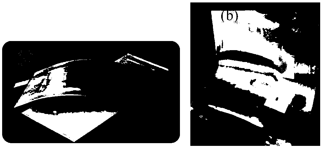
Flexible thin film cell
A flexible thin film and battery technology, applied in primary batteries, dry batteries, equipment for manufacturing primary batteries, etc., can solve the problems of reduced battery capacity, reduced battery performance, and easy formation of wrinkles
- Summary
- Abstract
- Description
- Claims
- Application Information
AI Technical Summary
Problems solved by technology
Method used
Image
Examples
Embodiment 1
[0167] according to Figure 4 The roll-to-roll printing production schematic diagram, the flexible thin film battery is prepared by printing from the inside to the outside; the printing process needs to be dried before printing the next layer; that is, the positive electrode layer is printed, and after drying, the printed carbon layer is used as the positive electrode current collector. After drying, a negative electrode layer is printed, and after drying, a carbon layer is printed as a negative electrode current collector.
[0168] The separator is cellulose paper; the thickness is 40 μm;
[0169] The thickness of the positive electrode layer is 100 μm; the composition of the positive electrode slurry is shown in Table 1;
[0170] The thickness of the negative electrode layer is 50 μm; the composition of the negative electrode slurry is shown in Table 1;
[0171] The positive current collector layer is a carbon layer with a thickness of 20 μm;
[0172] The negative electro...
Embodiment 2
[0177] A flexible thin-film battery was prepared according to the method of Example 1. The separator used a 30um thick PDVF film with a void rate of 80%. The materials and thicknesses of other layers were the same, and 8μm SiO was printed between the separator and the positive electrode layer 2 as a ceramic layer.
[0178] The performance of the flexible film battery obtained in Example 2 is detected, and the electrolyte is 2M ammonium chloride and 2M zinc chloride solution; the battery capacity of 1.45mAh / cm is detected 2 , after bending 1000 times, the battery voltage remains at 1.5V, and the detection capacity is 1.45mAh / cm 2 .
Embodiment 3
[0179] Example 3 Series flexible thin film battery
[0180] Preparation of 3V output Zn / MnO 2 Battery. Zn / MnO 2 The battery has the advantages of safety and environmental protection, but its low voltage output limits its application. The driving voltage of conventional integrated circuit chips is 3V. The Zn / MnO2 battery with 3V output can be easily prepared through the method disclosed in the invention. like Figure 4 As shown, printing unit 1 was prepared by roll-to-roll printing: positive and negative electrodes (50 μm) and collector carbon layer (20 μm) were printed on the separator layer (40 μm cellulose paper) up and down. It should be noted that the carbon layer current collector on the positive electrode can be printed thinner to reduce the production cost of the battery, and also reduce the overall thickness of the battery. Its thickness can be controlled at 1 to 5 μm. The printed battery unit 2 was prepared in the same way; the type and thickness of the separato...
PUM
| Property | Measurement | Unit |
|---|---|---|
| Thickness | aaaaa | aaaaa |
| Thickness | aaaaa | aaaaa |
| Thickness | aaaaa | aaaaa |
Abstract
Description
Claims
Application Information
 - R&D
- Intellectual Property
- Life Sciences
- Materials
- Tech Scout
- Unparalleled Data Quality
- Higher Quality Content
- 60% Fewer Hallucinations
Browse by: Latest US Patents, China's latest patents, Technical Efficacy Thesaurus, Application Domain, Technology Topic, Popular Technical Reports.
© 2025 PatSnap. All rights reserved.Legal|Privacy policy|Modern Slavery Act Transparency Statement|Sitemap|About US| Contact US: help@patsnap.com


