Load adaptive constant current source device
A constant current source and self-adaptive technology, which is applied in the direction of instruments, control/regulation systems, and adjustment of electrical variables, etc., can solve problems such as load or instrument damage, output current exceeding the limit current, etc.
- Summary
- Abstract
- Description
- Claims
- Application Information
AI Technical Summary
Problems solved by technology
Method used
Image

Examples
Embodiment 1
[0038] Example 1 Overall structure of the present invention
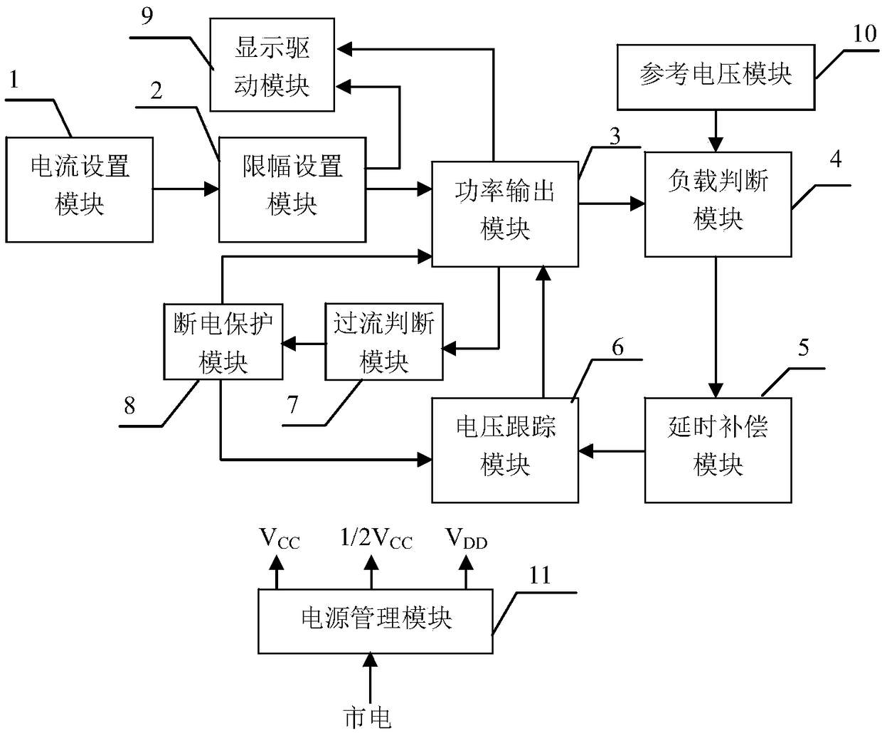
[0039] The overall structure of the present invention is as figure 1 As shown, there are current setting module 1, limit setting module 2, power output module 3, load judgment module 4, delay compensation module 5, voltage tracking module 6, overcurrent judgment module 7, power failure protection module 8, display driver Module 9, reference voltage module 10, power management module 11, front panel 12; among them, current setting module 1 is connected to limit setting module 2, and limit setting module 2 is also connected to power output module 3 and display drive module 9, respectively, The power output module 3 is respectively connected to the display drive module 9, the load judgment module 4, and the overcurrent judgment module 7, the reference voltage module 10 is connected to the load judgment module 4, the load judgment module 4 is connected to the delay compensation module 5, and the delay compensation module 5...
Embodiment 2
[0040] Embodiment 2 The current setting module of the present invention
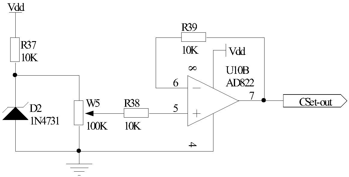
[0041] The current setting module 1 of the present invention belongs to the prior art, and can be conventionally designed according to actual needs, or can be designed such as image 3 In the structure shown, one end of the resistor R37 is connected to the power supply Vdd, the other end is connected to the cathode of the Zener diode D2 and a fixed end of the sliding rheostat W5, the anode of the Zener diode D2 is grounded, and the other fixed end of the sliding rheostat W5 is grounded. One end of R38 is connected to the sliding wire end of the sliding rheostat W5, the other end is connected to the non-inverting input end of the operational amplifier U10B, the inverting input end of the operational amplifier U10B is connected to one end of the resistor R39, and the other end of the resistor R39 is connected to the output end of the operational amplifier U10B. And as the output terminal of the current setting...
Embodiment 3
[0043] Embodiment 3 The limit setting module of the present invention
[0044] The limit setting module 2 of the present invention belongs to the prior art, and can be conventionally designed according to actual needs, or the structure provided in this embodiment can also be adopted, such as Figure 4 As shown, one end of the resistor R42 is used as the input terminal of the limiter setting module 2, marked as port CL-in, the other end is connected to the non-inverting input terminal of the operational amplifier U11B and the anode of the diode D3, and the negative electrode of the diode D3 is connected to the output of the operational amplifier U10A The other end of the resistor R41 is connected to the inverting input end of the operational amplifier U10A, the non-inverting input end of the operational amplifier U10A is connected to one end of the resistor R40, and the other end of the resistor R40 is connected to the sliding end of the sliding rheostat W6. One end of the varistor...
PUM
 Abstract
Description
Claims
Application Information