
Intelligent dredging vehicle for deep inspection well

A technology for dredging vehicles and deep inspection wells, which is applied to waterway systems, earth movers/excavators, water supply devices, etc., and can solve the problems of ground pollution, high labor intensity, and lack of oxygen at the entrance of inspection wells, so as to ensure life safety, High degree of intelligence, easy to operate and use

Inactive Publication Date: 2019-02-22
李聚恒
View PDF0 Cites 2 Cited by
  • Summary
  • Abstract
  • Description
  • Claims
  • Application Information

AI Technical Summary

Problems solved by technology

The existing cleaning methods mainly rely on the operators to go down the inspection shaft for manual cleaning. Because the silt and sewage in the deep inspection shaft will produce a large amount of methane gas, it will cause serious hypoxia underground and pose a serious threat to the lives of the operators who go down the well.
In addition, because the bottom of the inspection well is deep and dark, it also brings inconvenience to the construction of the operators.
However, the silt, sand, and bricks and stones cleaned from the inspection well cannot be directly transported away, which will cause certain pollution on the ground at the inspection well mouth.
When cleaning the inspection well, the labor intensity of the operators is high, and the operation efficiency is low

Method used


Image

  • Intelligent dredging vehicle for deep inspection well
  • Intelligent dredging vehicle for deep inspection well
  • Intelligent dredging vehicle for deep inspection well

Examples


Embodiment Construction

[0018] Below in conjunction with accompanying drawing, the deep inspection shaft intelligent dredging of the present invention is described in detail.

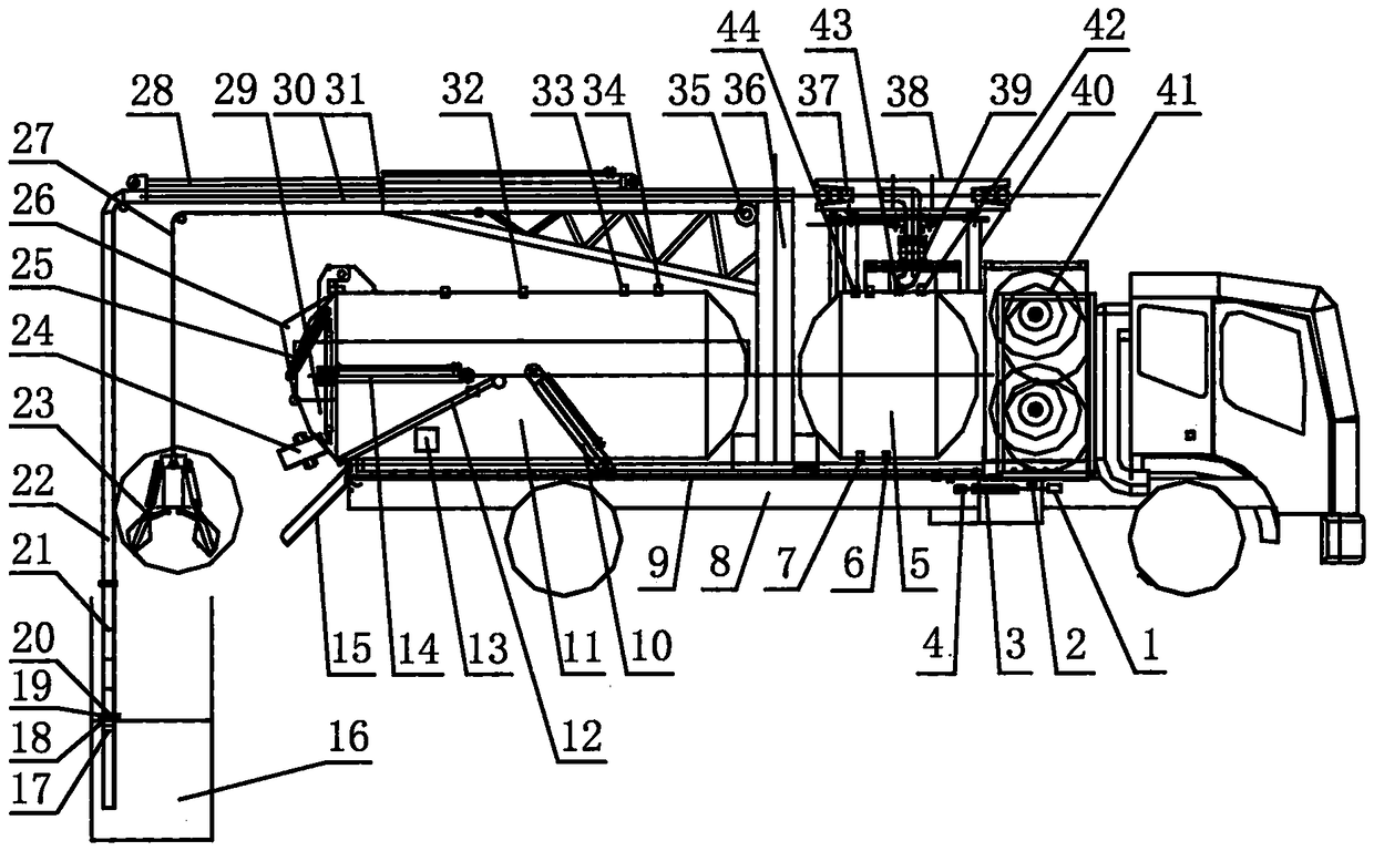
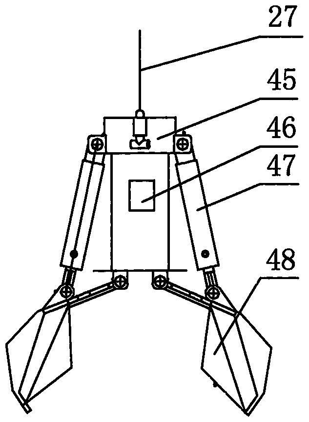
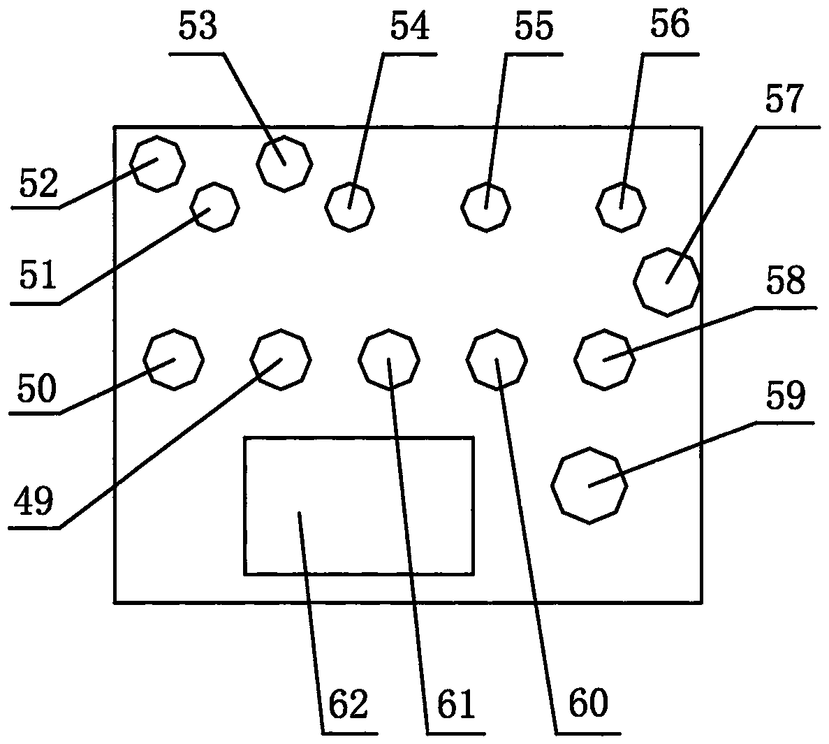
[0019] see Figure 1 to Figure 3, the intelligent dredging of the deep inspection well of the present invention comprises a chassis 8, a subframe 9 is set on the chassis 8, a gas cabinet 41 and a clean water tank 5 are arranged at the front of the subframe 9, and the top of the clean water tank 5 is provided with a ball valve. The water inlet 42 and the air inlet 43 of switch, the bottom is provided with water outlet 6, and the rear portion of auxiliary frame 9 is established dirt suction tank 11. The tail of the sewage suction tank 11 is connected with the subframe 9 through a rotating shaft, and a sewage suction tank lifting cylinder 10 connected with the sewage suction tank 11 is arranged on the subframe 9, and the sewage suction tank can be rotated around the rotating shaft through the sewage suction tank lifting cylinder ...


PUM


Abstract

The invention provides an intelligent dredging vehicle for a deep inspection well, which is characterized in that a clean water tank and a sewage absorption tank are arranged on an auxiliary frame ofa chassis, and a sewage box is arranged on a rear cover of the sewage absorption tank; a suspension arm is arranged on an upright post between the sewage absorption tank and the clean water tank, anda rotating joint and a sewage absorption pipe turntable are arranged on the clean water tank; a left power take-off device and a right power take-off device are arranged below an engine, one power take-off device is connected with a vacuum pump connected with the sewage absorption tank, the other power take-off device is connected with an oil pump and an air compressor component, one end of an airoutlet pipe of an air storage bag is connected with an air inlet of a clean water tank through a three-way valve, the other end of the air outlet pipe of the air storage bag and an air outlet pipe connected with a water outlet of the clean water tank come together to form a water-gas pipe through a water-gas conversion slide valve; the sewage absorption pipe and the water-gas pipe are coiled on the sewage absorption pipe turntable and are connected with the suspension arm; the other end of the sewage absorption pipe is provided with a sewage disc, a manipulator, a camera and a signal receiving device, and a claw bucket device provided with the camera and the signal receiving device is arranged at the end part of a steel wire rope wound on a steel wire rope winding and unwinding device ofthe suspension arm. The vehicle achieves the intelligent cleaning of dry and wet inspection wells, and has the advantages of low labor intensity, safety, high efficiency and no pollution.

Description

technical field [0001] The invention relates to a dredging vehicle, in particular to an intelligent dredging vehicle for deep inspection wells, which is a dredging vehicle for removing sludge, masonry, tiles, etc. in deep inspection wells. Background technique [0002] There are often silt, sewage, masonry tiles, etc. in the deep inspection shaft, which need to be cleaned irregularly to avoid blocking the drainage of the inspection shaft. The existing cleaning methods mainly rely on the operators to go down the inspection shaft for manual cleaning. Because the silt and sewage in the deep inspection shaft will produce a large amount of methane gas, it will cause severe hypoxia underground and pose a serious threat to the lives of the operators who go down the shaft. In addition, because the bottom of the inspection well is deep and dark, it also brings inconvenience to the construction of the operators. And the silt sand and masonry blocks that are cleaned out from the inspe...

Claims


Application Information

Patent Timeline
Patent Type & Authority Applications(China)
IPC IPC(8): E03F7/10E02F5/28
CPCE03F7/10E02F5/28
Inventor 李聚恒
Owner 李聚恒
Learn More