
Ultra-flexible multi-strand combined carbon fiber composite core wire and manufacturing process thereof

A carbon fiber and composite core technology, applied in the direction of cable/conductor manufacturing, conductors, insulated conductors, etc., can solve the problem that the advantages of stranded shape integrity no longer exist, and cannot well meet the needs of use, use stability, and reliability No high problems, to achieve the effect of good consistency, high strength and uniform force

Pending Publication Date: 2019-02-22
HEBEI SILICON VALLEY CHEM CO LTD +1
View PDF0 Cites 2 Cited by
  • Summary
  • Abstract
  • Description
  • Claims
  • Application Information

AI Technical Summary

Problems solved by technology

[0002] Conductor mandrel is used as the supporting core material of the wire. With the continuous advancement of material technology, it has become a well-known technical solution in the art to use organic composite materials as the mandrel core material; Multi-strand core wire stranding form, single core rod-shaped core wire is easy to bend and damage, resulting in frequent wire breakage accidents; multi-strand core wire stranding form twists and fixes multiple strands of core wire in a helical manner, even The final shape is strengthened and fixed by dipping. Compared with the single-strand form, the multi-strand mandrel has significantly improved rigidity and winding bending ability. Compared with the single-strand form, the same amount of material is made The cross-section of the carbon fiber composite mandrel wire is increased, which greatly improves the transmission capacity of the wire and can significantly reduce the wire loss;
[0003] However, the existing mandrel in the form of twisted multi-strand core wires is prone to joint integrity damage after one core wire is bent, damaged or broken, and the bending fatigue damage of the remaining core wires during bending and winding will increase significantly. Highly prone to breakage, loss of stranded shape integrity
Therefore, the use stability and reliability of the existing helically stranded mandrel structure are not high. In addition, due to the different stranding forms of each single path, it cannot be guaranteed to break at the same time when the force is applied, and the overall strength is small.
However, in some special occasions, it still cannot meet the needs of use well.

Method used


Image

  • Ultra-flexible multi-strand combined carbon fiber composite core wire and manufacturing process thereof
  • Ultra-flexible multi-strand combined carbon fiber composite core wire and manufacturing process thereof

Examples


Embodiment 1

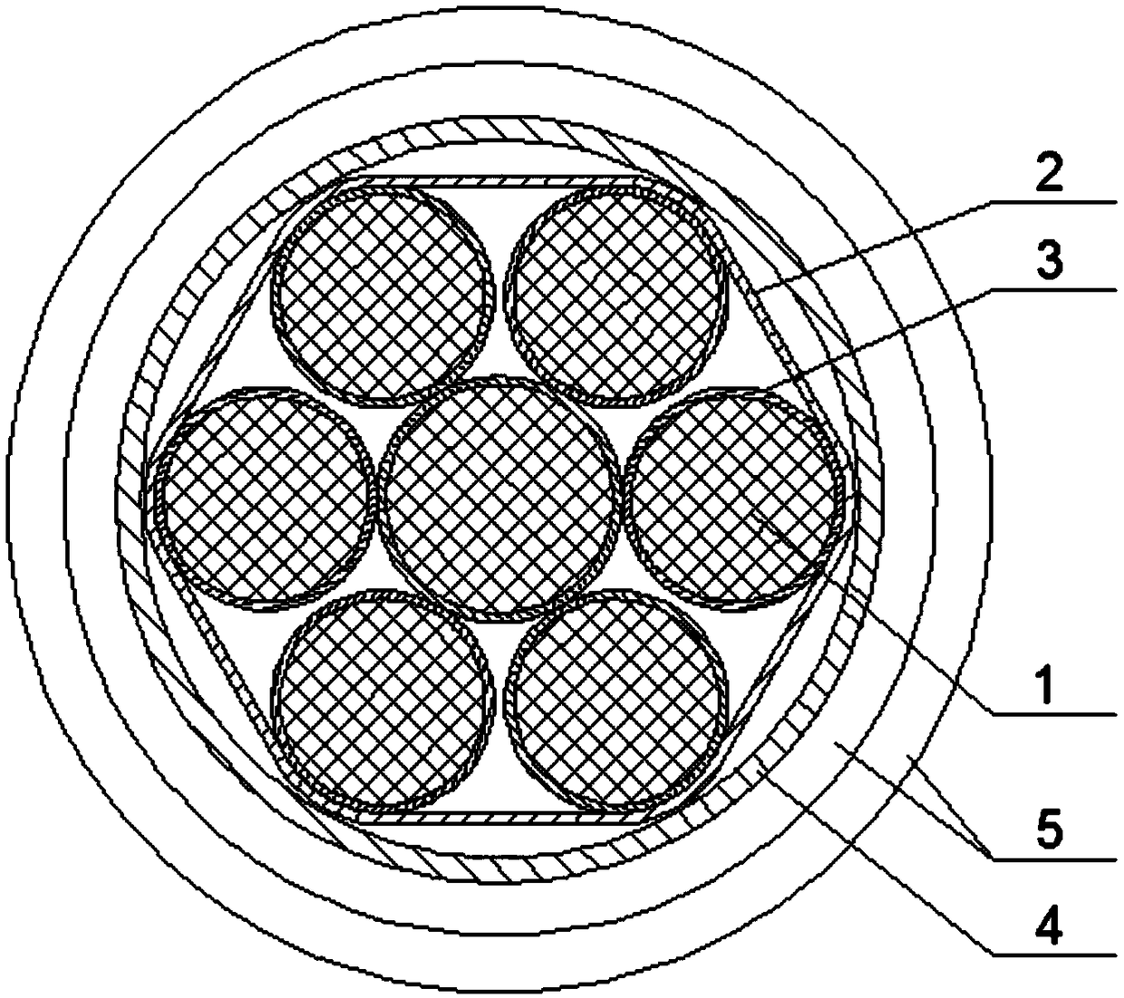
[0028] Embodiment 1, 400 / 50 specification, such as figure 1 As shown, the carbon fiber composite core 1 is a mandrel with a diameter of 3.0mm formed by impregnating eight T700 12K carbon fiber filaments with high-temperature resin and pultruded with a glass ribbon with a thickness of 0.6mm; the strength is 2600MPa; calculated by mass percentage , carbon fiber content 72%, resin content 18%, glass fiber content 10%; DMA method storage modulus glass transition temperature Tg value 230 ℃. The preferred glass fiber fabric reinforcement material of the cladding layer 2 has a thickness of 1.1mm, and the number of carbon fiber composite cores 1 in the carbon fiber composite core group is 7, one in the middle, and the other six are parallel and merged around it, Arranged in a circular array;

[0029] The thickness of the aluminum extruded cladding 4 is 0.6mm.

[0030] The aluminum strand layer 5 is a soft aluminum alloy trapezoidal strand layer, which is arranged in two layers, and ...

Embodiment 2

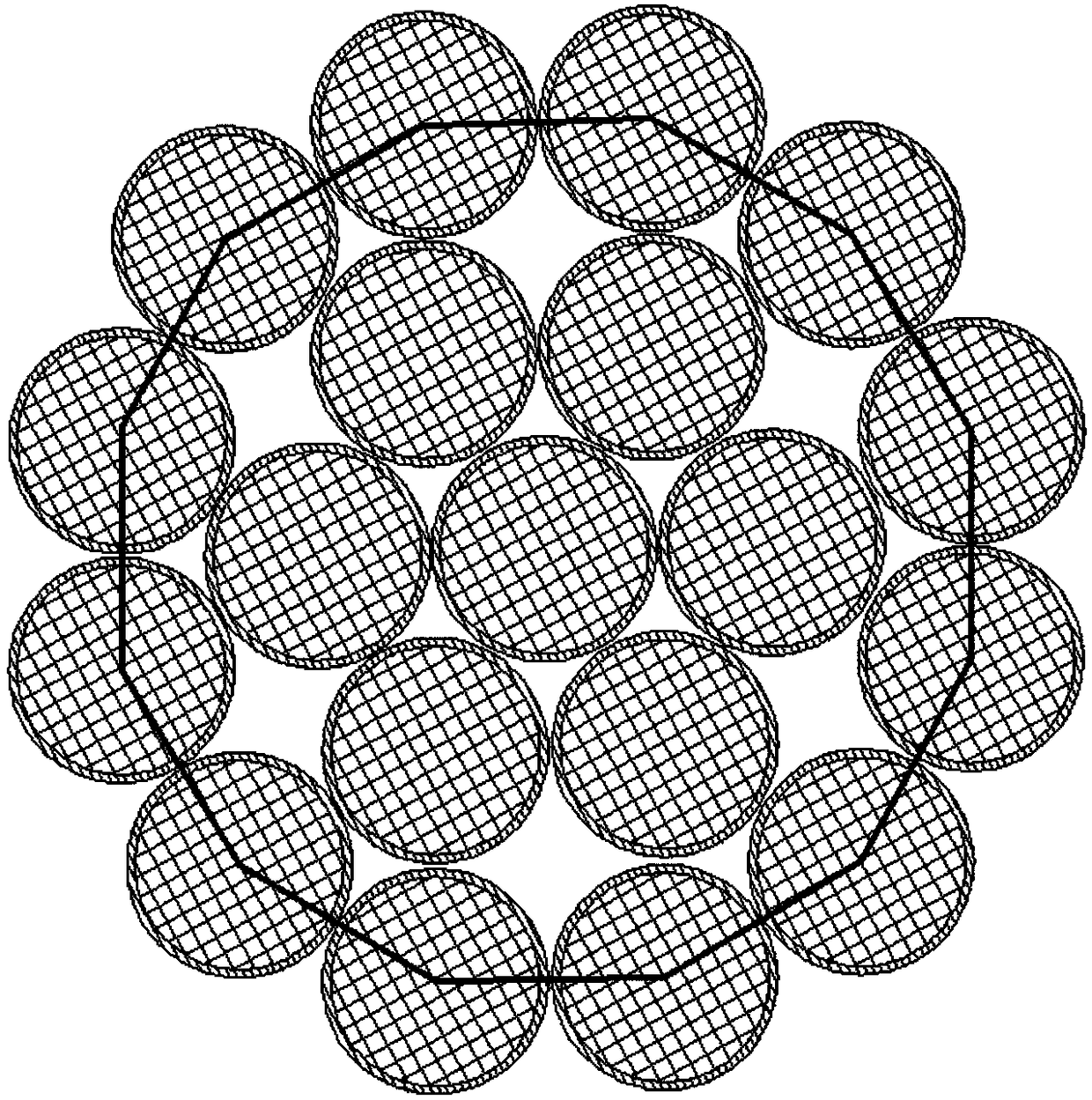
[0036] Example 2, such as figure 2 As shown, as another form of carbon fiber composite mandrel in Example 1, the number of carbon fiber composite cores 1 in the carbon fiber composite core group is 19, and three layers are arranged in total, with one mandrel in the center and 6 in the second layer. , 12 in the third layer.

[0037] The mandrels of the outer layer and the sub-outer layer are evenly arranged on the circumference around the core layer. In the above-mentioned three-layer structure, the connection line between the axes of the carbon fiber composite core 1 located at the periphery is a regular polygonal structure;

Embodiment 3

[0038]Embodiment 3, as the same structure as Embodiment 2, the number of carbon fiber composite cores 1 in the carbon fiber composite core group is 37, and four layers are arranged in total; 6, 12 on the third floor, and 18 on the fourth floor. The connecting lines between the axes of the carbon fiber composite core 1 located at the periphery are regular polygonal structures.


PUM

PropertyMeasurementUnit
Diameteraaaaaaaaaa
Strengthaaaaaaaaaa
Thicknessaaaaaaaaaa

Abstract

The invention discloses an ultra-flexible multi-strand combined carbon fiber composite core wire and a manufacturing process thereof. The wire includes a core rod and a conductive metal layer wrappedaround the core rod. The core rod includes a group of carbon fiber composite cores with circular cross section. The axes of the carbon fiber composite cores in the carbon fiber composite core group are arranged in parallel. A connection line of the axes of the carbon fiber composite cores located at the periphery of the carbon fiber composite core group constitutes a regular polygon structure. Theouter layer of the carbon fiber composite cores at the periphery of the carbon fiber composite core group are also wrapped in an aluminum foil or tin foil coating layer. A viscous glass fiber reinforcing layer is arranged on the inner layer of the aluminum foil or tin foil coating layer. The conductive metal layer includes an aluminum extrusion layer and an aluminum strand layer which are wrappedaround the coating layer in order. The ultra-flexible multi-strand combined carbon fiber composite core wire and the manufacturing process thereof overcome the defects of the prior art. The core rodis improved in bending and winding properties, enhanced in strength, improved in humidity and heat, ozone and ultraviolet aging resistance, and remarkably improved in stability and reliability of use.Moreover, the core rod can be prefabricated as a separate product so as to simplify the production process.

Description

technical field [0001] The invention belongs to the technical field of overhead wires, and in particular relates to a super-flexible multi-strand combined carbon fiber composite core wire and a manufacturing process thereof. Background technique [0002] Conductor mandrel is used as the supporting core material of the wire. With the continuous advancement of material technology, it has become a well-known technical solution in the art to use organic composite materials as the mandrel core material; Multi-strand core wire stranding form, single core rod-shaped core wire is easy to bend and damage, resulting in frequent wire breakage accidents; multi-strand core wire stranding form twists and fixes multiple strands of core wire in a helical manner, even The final shape is strengthened and fixed by dipping. Compared with the single-strand form, the multi-strand mandrel has significantly improved rigidity and winding bending ability. Compared with the single-strand form, the sam...

Claims


Application Information

Patent Timeline
IPC IPC(8): H01B9/00H01B7/18H01B7/04H01B7/02H01B7/28H01B7/282H01B7/29H01B13/00H01B13/08H01B13/22H01B13/26
CPCH01B7/02H01B7/04H01B7/1825H01B7/183H01B7/1875H01B7/188H01B7/28H01B7/2806H01B7/2825H01B7/292H01B9/006H01B9/008H01B13/00H01B13/08H01B13/22H01B13/26Y02A30/14
Inventor 宋志强齐保军宋利强宋聚强宋福如
Owner HEBEI SILICON VALLEY CHEM CO LTD
Learn More