Surface-slotted surface-mounted permanent magnet synchronous motor rotor structure

A permanent magnet synchronous motor, rotor structure technology, applied in the magnetic circuit shape/style/structure, magnetic circuit rotating parts, magnetic circuit and other directions, can solve the problems of reducing the utilization rate of rotor core, air gap magnetic field distortion, etc. Utilization rate, convenient processing, and the effect of facilitating installation

Inactive Publication Date: 2019-02-22
XI AN JIAOTONG UNIV
View PDF5 Cites 4 Cited by
  • Summary
  • Abstract
  • Description
  • Claims
  • Application Information

AI Technical Summary

Problems solved by technology

[0006] Since the permanent magnets in the surface-mounted permanent magnet synchronous motor are placed on the surface of the rotor, the magnetic field strength of the surface part of the rotor core is highly sa

Method used


Image

  • Surface-slotted surface-mounted permanent magnet synchronous motor rotor structure
  • Surface-slotted surface-mounted permanent magnet synchronous motor rotor structure
  • Surface-slotted surface-mounted permanent magnet synchronous motor rotor structure

Examples


Embodiment 1

[0084] Take a 2kW 12-slot 8-pole permanent magnet motor as an example, use Ansoft Maxwell 2D motor electromagnetic field calculation software to perform electromagnetic calculations on the four proposed permanent magnet motors with different slotted rotor structures. The results are as follows Figure 3a~Figure 3e As shown, the obtained various magnetic field line distribution diagrams and magnetic field distribution cloud diagrams of various rotor structure motors can be seen from the diagrams that the rotor magnetic field distribution of the rotor surface slot structure of the present invention is more uniform, and the rotor core utilization rate is higher.

Embodiment 2

[0086] Taking a 2kW 12-slot 8-pole permanent magnet motor as an example, using Ansoft Maxwell 3D motor electromagnetic field calculation software to perform electromagnetic calculations on the four proposed permanent magnet motors with different slotted rotor structures, the results are as follows Figure 4a~Figure 4e Shown, the obtained various rotor structure motor magnetic density cloud map. It can be seen from the figure that the rotor magnetic field distribution of the rotor surface slotted structure of the present invention is more uniform, and the rotor core utilization rate is higher.

Embodiment 3

[0088] Taking a 2kW 12-slot 8-pole permanent magnet motor as an example, we give a schematic diagram of filling the slotted rotors of the four surface mount permanent magnet synchronous motors with non-magnetic and conductive fillers, such as Figure 5a ~ Figure 5d As shown in the figure, 10 is a non-magnetic and non-conductive filler. It can be seen from the figure that after filling the surface of the rotor, the surface of the rotor is smoother, which can reduce the wind wear of the motor.

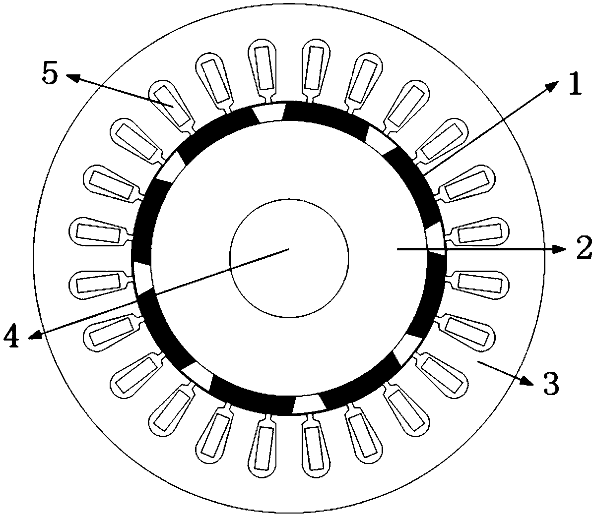
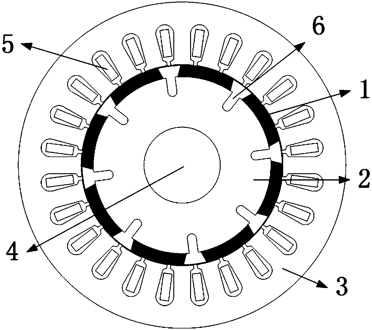
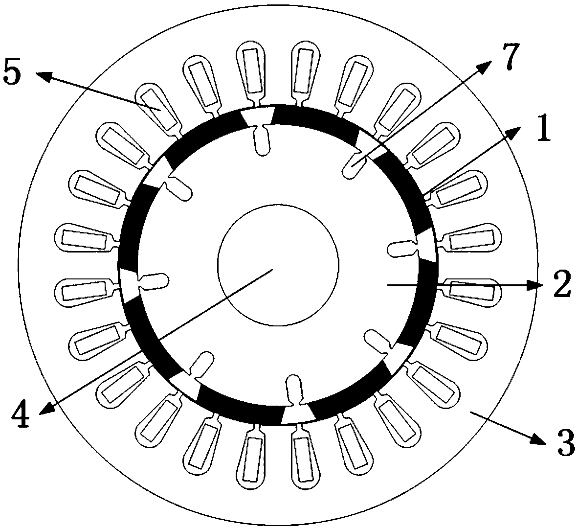
[0089] To sum up, the surface-mounted real-rotor surface-mounted high-efficiency permanent magnet synchronous motor rotor disclosed in the present invention, the specific implementation method of this new surface-slotted real-rotor surface-mounted high-efficiency permanent magnet synchronous motor is: The core part between the permanent magnets of each pole of the magnetic synchronous motor rotor is slotted to form radial slots (U open slot, U half closed slot, V open slot and V half closed ...


PUM

PropertyMeasurementUnit
Notch widthaaaaaaaaaa

Abstract

The invention discloses a surface-slotted surface-mounted permanent magnet synchronous motor rotor structure and belongs to the design field of a high-performance permanent magnet motor body. The technical solution is that the core portion between permanent magnets in each pole of the surface-mounted permanent magnet synchronous motor rotor is provided with a radial slot filled with a non-magneticand non-conductive filler. The air gap distribution, the rotor core structure, an air gap and a rotor magnetic circuit can be changed through the slot between the positive and negative poles of the permanent magnets, thereby optimizing the rotor magnetic field distribution during the operation of the motor, weakening the surface magnetic saturation of the rotor, improving the utilization rate ofthe rotor core, and reducing rotor-side hysteresis loss and eddy current loss. Therefore, the invention can provide important theoretical support and technical support for the development of a new generation of high-efficiency surface-mounted permanent magnet synchronous motor.

Description

Technical field [0001] The invention belongs to the field of high-performance permanent magnet motor body structure design, and particularly relates to a surface slotted surface mount permanent magnet synchronous motor rotor structure. Background technique [0002] The application prospects of high-efficiency rare earth permanent magnet motors are very broad, and they can be used in engineering fields such as mechanical engineering, power production, steel smelting, chemical fiber, light industry, textile, petrochemical, printing, transportation, mining, military and aerospace. It is matched with the "three machines and one pump" fan, compressor, refrigerator and water pump. It has unique advantages that induction motors can't match. Its speed is constant, the output torque is large, the efficiency is high, and the power factor is high. [0003] The permanent magnet synchronous motor is excited by permanent magnets and does not require additional excitation windings, which improves...

Claims


Application Information

Patent Timeline
IPC IPC(8): H02K1/27H02K1/24H02K1/26
CPCH02K1/24H02K1/265H02K1/278
Inventor 张冬冬安睿驰何宏景卜立潇褚帅君张建松
Owner XI AN JIAOTONG UNIV
Why Eureka
Try Eureka