High-efficiency coil type heat exchange evaporator and heat exchange method

A tubular heat exchange and evaporator technology, which is used in evaporators/condensers, lighting and heating equipment, refrigeration components, etc. and other problems, to achieve the effect of improving steam quality, less consumables, and small gaseous resistance

Pending Publication Date: 2019-02-26
沈阳天洁环保新能源有限公司 +1
View PDF0 Cites 0 Cited by
  • Summary
  • Abstract
  • Description
  • Claims
  • Application Information

AI Technical Summary

Problems solved by technology

[0008] In order to solve the technical problems in the prior art such as slow heat transfer rate, large heat exchanger volume and large space occupation, and much water in the gas after heat transfer, the purpose of the present invention is to provide a high-efficiency evaporation, low resistance, fast heat transfer rate, High-efficiency coil heat exchange evaporator with small volume, small footprint, high gas evaporation efficiency, and low water content in evaporated gas

Method used


Image

  • High-efficiency coil type heat exchange evaporator and heat exchange method

Examples


Embodiment 1

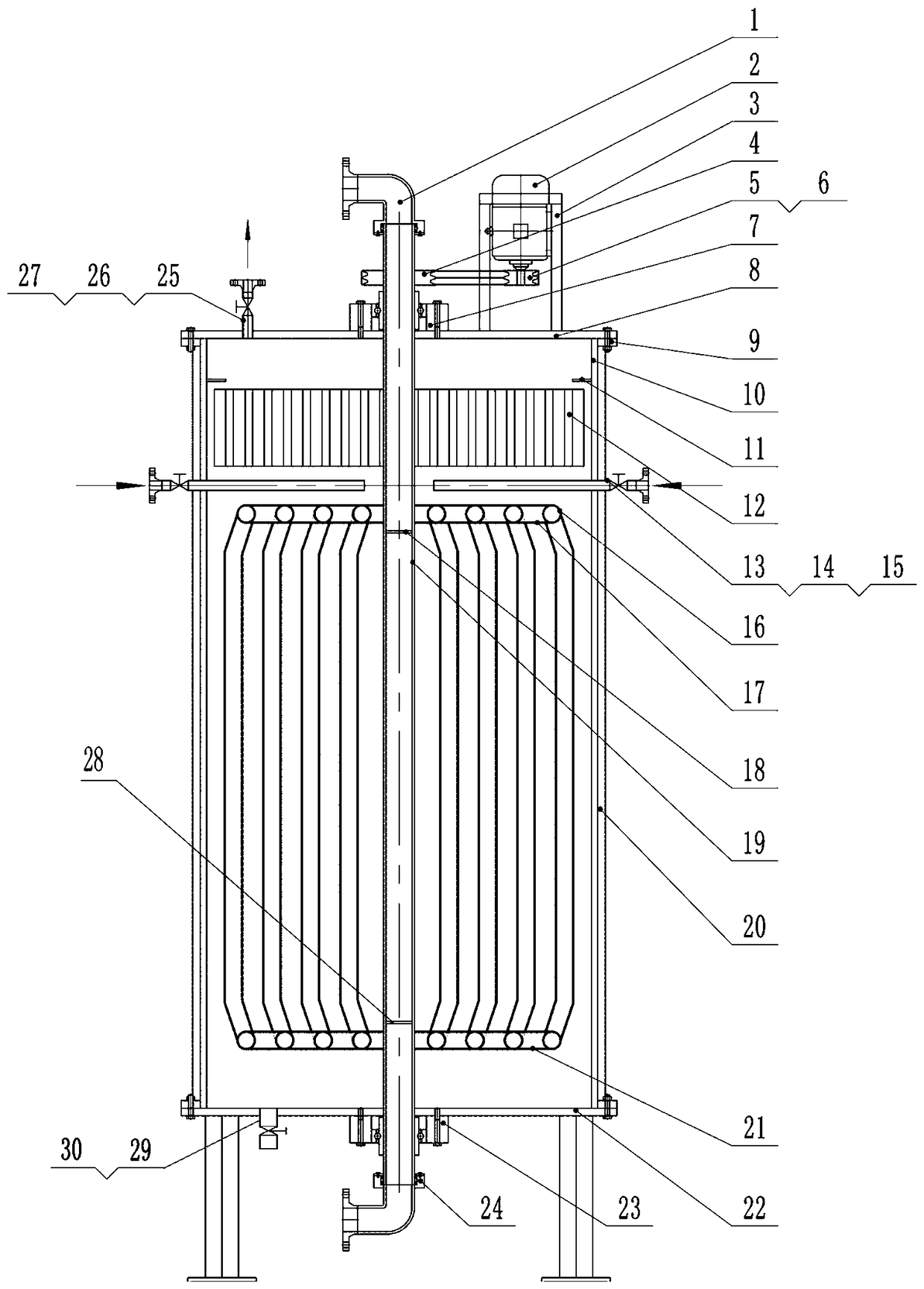
[0039] Embodiment one, such as figure 1As shown, including a hollow cylinder (10), a tubular rotating shaft (19) is installed in the center of the cylindrical body (10), and the upper and lower ports of the tubular rotating shaft (19) respectively pass through the upper rotary joint (1), the lower The swivel joint (24) is connected with the external fixed water pipe, and the tubular rotating shaft (19) is respectively fixed on the upper cover plate (8) and the lower cover plate outside the cylinder (10) through the upper end bearing (7) and the lower end bearing (23) (22), the upper cover plate (8) and the lower cover plate (22) are sealed and connected to the cylinder body (10) through the cover plate flange (9), and the upper cover plate (8) is equipped with frequency conversion adjustable speed Drive device, variable frequency drive device is composed of variable frequency motor (2), motor bracket (3), motor pulley (5), shaft pulley (4) and V-belt (6), motor bracket (3) is ...

Embodiment 2

[0050] Embodiment 2, according to the diameter of the cylindrical body (10), a plurality of evenly arranged rotary tube devices can be arranged radially around the tubular rotating shaft (19), that is, with the tubular rotating shaft (19) as the center of the circle, radially set There are multiple layers of small-diameter tubes (16) arranged in concentric circles to form a group of small-diameter tubes arranged in a multi-layer ring. The upper end of each small-diameter tube (16) is firmly fixed on the upper end of the tubular shaft (19). On the last annular pipe (17), the lower end of every screw small-diameter pipe (16) is firmly fixed on the lower annular pipe (21) communicated with the lower end of the tubular rotating shaft (19).

[0051] Because it is a multi-layer small-diameter tube group composed of multiple small-diameter tubes connected in parallel, the liquid resistance in the small-diameter tube is very small, the volume of the cylinder outside the small-diameter ...

Embodiment 3

[0052] Embodiment 3, the blade on the impeller bracket can also be set as an integral blade, and there are a plurality of louver-shaped air grooves in the vertical direction on the blade, and the louvers of the adjacent louver-shaped air grooves are opened in opposite directions, so that through the louver The airflow turbulence of the air groove is stronger.

[0053] Materials such as containers, spiral tubes, and rotating vane plates are designed according to the needs of heat exchange liquids and evaporating liquids. Materials such as copper, stainless steel, iron, and aluminum can be used. The size of the container, diameter, length, and number of tubes are determined according to the energy conversion power. Sure.

[0054] The evaporating surface area of ​​the evaporating liquid in the present invention is very large, and the rotating liquid pipe ensures that a very stable liquid film is formed on the outer surface of the coiled pipe. In addition, the wind speed formed by...


PUM


Abstract

The invention discloses a high-efficiency coil type heat exchange evaporator which comprises a hollow cylinder body; a tubular rotating shaft is installed in the center of the cylinder body, and the tubular rotating shaft is rotated by a variable frequency driving device. The upper and lower ends of the tubular rotating shaft are respectively provided with rotary joints communicating with the external fixed water pipe, and blocking plates are installed at the upper and lower ends of the tubular rotating shaft tube; a set of rotary vane device and a rotary tube device are respectively installedabove and below the tubular rotating shaft in the cylinder body, and the rotary tube device and the rotary vane device rotate together with the tubular rotating shaft; a liquid inlet pipe is radiallymounted on the inner wall of the cylinder between the rotary tube device and the rotary vane device, and an outlet pipe for evaporating gas is disposed at the top of the cylindrical body, and an insulating layer is further disposed outside the cylinder. The invention has high evaporation efficiency, high liquid cooling efficiency, low consumables, compact and reasonable structure, small volume ofthe same capacity equipment, especially the gas after heat exchange is dehydrated, and the discharged gas has no droplets or droplets.

Description

technical field [0001] The invention belongs to the field of thermal energy engineering, and in particular relates to an improvement of a heat exchange evaporator structure and a heat exchange method with a dynamic multi-layer coil technical structure. Background technique [0002] Heat exchangers (also referred to as heat exchangers for short) are widely used in many fields as an important heat exchange equipment. In the field of thermal energy engineering, the efficiency of heat exchangers directly affects the efficiency of thermal systems or thermodynamic cycle systems, thereby affecting the utilization of energy. Energy shortage and environmental pollution have become one of the main problems restricting the sustainable development of human beings. Among them, how to improve the efficiency of energy utilization, heat exchangers have naturally become one of the equipment that people pay attention to. [0003] Heat exchangers include evaporators, condensers, intercoolers,...

Claims


Application Information

Patent Timeline
IPC IPC(8): F25B39/02
CPCF25B39/02
Inventor 陈闽钢陈坚
Owner 沈阳天洁环保新能源有限公司
Why Eureka
Try Eureka