Utility tunnel circulating type firefighting water system device and method and application thereof

A technology of comprehensive pipe gallery and system device, which is applied in fire rescue and other directions, can solve the problems of inability to apply comprehensive pipe gallery, etc., and achieve the effect of increasing water consumption and action time, strong practical operability, and simple operation

Pending Publication Date: 2019-03-01
CHINA ACAD OF BUILDING RES +1
View PDF9 Cites 2 Cited by
  • Summary
  • Abstract
  • Description
  • Claims
  • Application Information

AI Technical Summary

Problems solved by technology

[0005] In order to solve the problem that the existing water system fire extinguishing system cannot be applied to the comprehensive pipe gallery due to the limitation of water volume, and at the same time solve the problem of the collected water quality, the present invention provides a comprehensive pipe gallery circulating fire water system device, method and application. The device and The method can solve the problem of the water volume of the water system fire extinguishing system, and the collected water can be used in the continuous fire extinguishing of the comprehensive pipe gallery after a certain treatment

Method used


Image

  • Utility tunnel circulating type firefighting water system device and method and application thereof

Examples


Embodiment 1

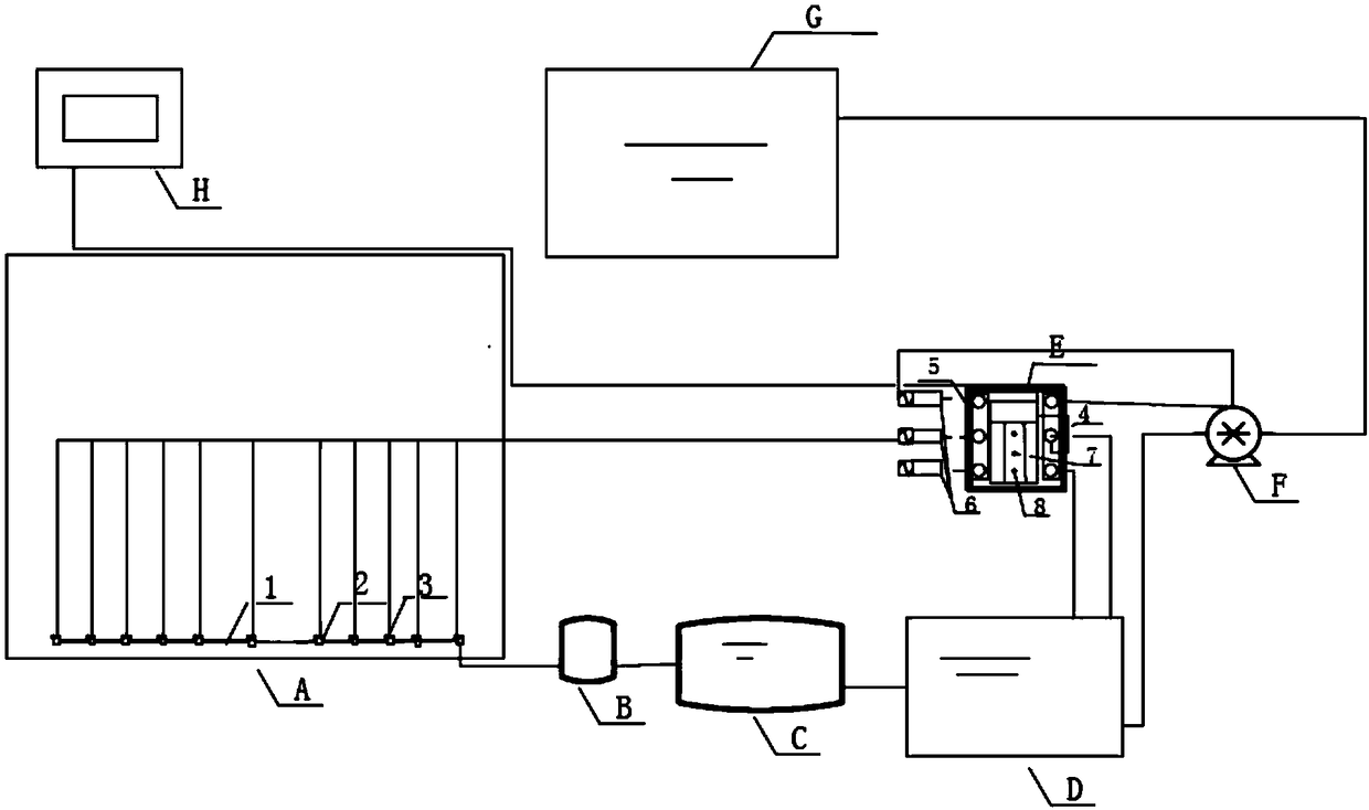
[0037] The pipe gallery adopts a water spray system with a design flow rate of 0.39m 3 / s, the design continuous supply time is 0.4h. When simulating a fire, start all the sprinklers in the fire compartment where the fire is located, and monitor the flow of the water system at the most unfavorable point. The design test time is 1h, and the results show that the flow rate of the nozzle at the most unfavorable point of the test is always greater than 0.39m 3 / s, and the water level of the original fire pool or water tank of the water spray system is not lower than the minimum effective water level.

Embodiment 2

[0039] The pipe gallery adopts a high-pressure water mist system with a design flow rate of 0.06m 3 / s, the design continuous supply time is 0.5h. When simulating a fire, start all the sprinklers in the fire compartment where the fire is located, and monitor the flow of the water system at the most unfavorable point. The design test time is 2 hours, and the results show that the flow rate of the nozzle at the most unfavorable point of the test is always greater than 0.06m 3 / s, and the water level of the original fire pool or water tank of the high-pressure water mist system is not lower than the minimum effective water level.

Embodiment 3

[0041] The pipe gallery adopts a medium-pressure fine water mist system with a design flow rate of 0.25m 3 L / s, the design continuous supply time is 0.5h. When simulating a fire, start all the sprinklers in the fire compartment where the fire is located, and monitor the flow of the water system at the most unfavorable point. The design test time is 1h, and the results show that the flow rate of the nozzle at the most unfavorable point of the test is always greater than 0.25m 3 / s, and the water level of the original fire pool or water tank of the medium pressure water mist system is not lower than the minimum effective water level.


PUM


Abstract

A utility tunnel circulating type firefighting water system device and method and application thereof belong to the technical field of fire safety. The utility tunnel circulating type firefighting water system device mainly comprises a collecting pipe, an opening, a water collecting well, a water processing system, a fire water tank, a control system and a fire pump which are arranged inside a utility tunnel; when fire breaks out, water sprayed by a fire extinguishing system can be collected into the collecting pipe through the walls and the ground of the utility tunnel and via the opening ofthe collecting pipe and then flow into the water collecting well; water in the water collecting well flows into the water processing system by gravity for biological treatment and settlement treatmentsequentially; water processed by the water processing system can flow into the fire water tank by gravity, and when the water inside the fire water tank meets minimum requirements on water capacity,the control system controls the fire pump to work to convey the water inside the fire water tank into an original fire water pool or tank of the utility tunnel; after fire is extinguished, the controlsystem can close the water pump and empty the water inside the utility tunnel circulating type firefighting water system device. The utility tunnel circulating type firefighting water system device is simple in operation and high in practicality.

Description

technical field [0001] The invention belongs to the technical field of fire safety, and relates to a circulating fire water system device, method and application of a comprehensive pipe gallery. Background technique [0002] The construction of comprehensive pipe gallery is an effective way to improve the healthy operation of the urban underground pipe network, reduce repeated excavation of the road surface, and improve the safe operation of the city. All the important pipelines for local life and production are laid in the comprehensive pipe gallery, and a fire extinguishing system should be installed in the comprehensive pipe gallery to control the scope of the fire. [0003] At present, the fire extinguishing system in the integrated pipe gallery can be divided into a water system fire extinguishing system and a dry powder fire extinguishing system according to the nature of the fire extinguishing agent. The water system fire extinguishing system mainly includes fine wat...

Claims


Application Information

Patent Timeline
Patent Type & Authority Applications(China)
IPC IPC(8): A62C35/58A62C35/68
CPCA62C35/58A62C35/68
Inventor 相坤李磊李宏文王靖波陈健张成
Owner CHINA ACAD OF BUILDING RES
Why Eureka
Try Eureka