Filtering material electret equipment and method

A filter material and electret technology, applied in the direction of filter separation, separation methods, chemical instruments and methods, etc., can solve the waste of resources, can not be used to manufacture a variety of different filter materials, etc., to achieve the effect of eliminating waste and polarization Robust, compact equipment

Inactive Publication Date: 2019-03-01
NORTHEASTERN UNIV
View PDF5 Cites 0 Cited by
  • Summary
  • Abstract
  • Description
  • Claims
  • Application Information

AI Technical Summary

Problems solved by technology

There have been relevant researches on the production and reproducibility of electret filter materials, but most of the existing products are disposable, resulting in a huge waste of resources
[0004] Moreover, existing equipment or manufacturing methods can maximize the electret performance of the filter material, especially the charge capacity, and cannot be used to manufacture a variety of different filter materials

Method used


Image

  • Filtering material electret equipment and method
  • Filtering material electret equipment and method
  • Filtering material electret equipment and method

Examples


Embodiment 1

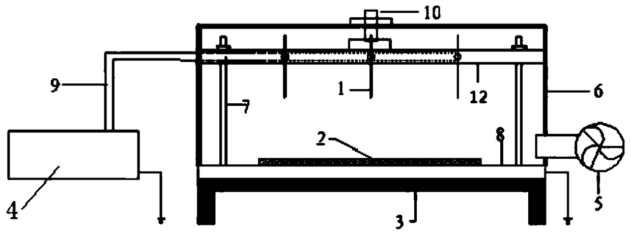
[0042] Such as figure 1 As shown, the temperature control heating device 3 is placed on the ground as a whole, and its upper space is completely covered by the insulating cover 6 . The insulating cover 6 can also cover the temperature control heating device 3 as a whole.

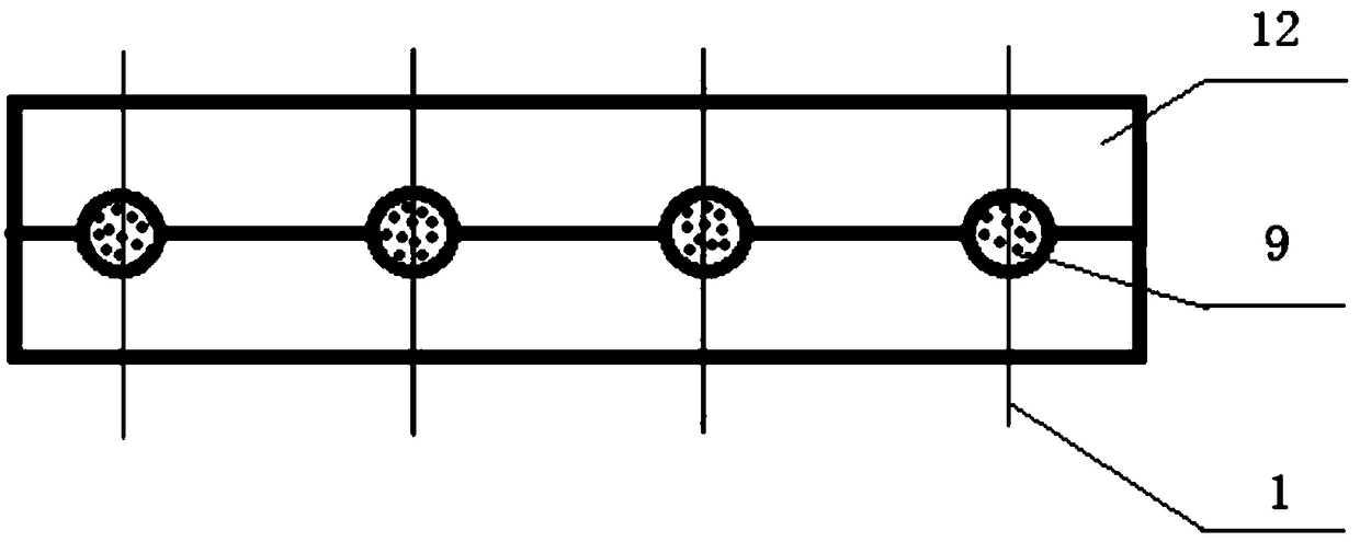
[0043] Most of the voltage-applying devices are arranged in the insulating cover 6, and the DC high-voltage power supply 4 is arranged outside and connected to the needle electrode 1 through the high-voltage wire 9, and the DC high-voltage power supply 4 is also grounded. The DC high-voltage power supply 4 has a voltage regulation range of 0kV-30kV, and has the functions of breakdown power cutoff and overcurrent power cutoff.

[0044] A plate electrode 8 is arranged on the temperature control heating device 3, and the plate electrode 8 is grounded. figure 1 The middle support rod 7 is fixed to the plate electrode 8 , and may actually be fixed to the temperature control heating device 3 or the insulating co...

Embodiment 2

[0056] S1, raw material 2 is PTFE (Poly tetrafluoroethylene, polytetrafluoroethylene) needle felt, PTFE is placed on the metal plate electrode 8, the insulating cover 6 is closed, and the distance between the needle electrode 1 and the plate electrode 8 is adjusted to 2cm;

[0057] S2, turn on the temperature control heating device 3, heat the PTFE to make its surface temperature reach 300°C;

[0058] S3, turn on the DC high-voltage power supply 4, the voltage between the needle electrode 1 and the plate electrode 8 is 15kV, and the electret time is 2 / 3h;

[0059] S4, turn off the temperature control heating device 3, keep the DC high-voltage power supply 4, turn on the cooling fan 5, reduce the surface temperature of PTFE to room temperature, and obtain the finished product;

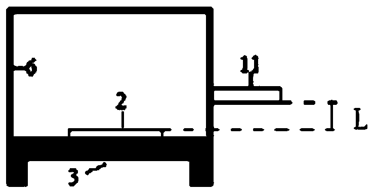
[0060] S5, pull out the plate electrode 8 from the insulating cover 6, and use the surface potential detector 11 to detect the quality of the finished product,

[0061] If qualified, take out the finis...

Embodiment 3

[0064] S1, raw material 2 is P84 (polyimide) filter material, place P84 on the metal plate electrode 8, close the insulating cover 6, adjust the distance between the needle electrode 1 and the plate electrode 8 to 2cm;

[0065] S2, turn on the temperature control heating device 3, and heat P84 to make its surface temperature reach 350°C;

[0066] S3, turn on the DC high-voltage power supply 4, the voltage between the needle electrode 1 and the plate electrode 8 is 18kV, and the electret time is 1.5h;

[0067] S4, turn off the temperature control heating device 3, keep the DC high-voltage power supply 4, turn on the cooling fan 5, reduce the surface temperature of P84 to room temperature, and obtain the finished product;

[0068] S5, pull out the plate electrode 8 from the insulating cover 6, and use the surface potential detector 11 to detect the quality of the finished product,

[0069] If qualified, take out the finished product;

[0070] If unqualified, repeat S1-S5.


PUM


Abstract

The invention relates to filtering material electret equipment. The equipment comprises a temperature control heating device, a voltage applying device, a cooling device and a protection device; needle tips of needle electrodes are arranged opposite to a plate surface of a plate electrode, the needle electrodes slide relative to the plate electrode, and an electret working space is formed betweenthe needle electrodes and the plate electrode; a direct-current power source is connected with the needle electrodes, and the plate electrode is grounded; a filtering material to be processed is disposed on the plate electrode; the protection device comprises an insulation cover. Preheating, electret operation, cooling and other work are completed in the same electret working space. The equipmentis compact in structure and high in integration. The insulation cover protects an equipment user, and the operation is safe. The temperature, the voltage and the electrode spacing are adjustable, andoptimal electret parameters are adjusted for different air filtering materials. For example, the temperature during the electret operation is adjusted to a melting temperature of a polymer, so that the electret stability is the highest, waste of the electret filtering materials is reduced to a large extent, and repeated use of the electret filtering materials is achieved.

Description

technical field [0001] The invention relates to the field of polymer electret filter material manufacturing, in particular to a filter material electret device and method. Background technique [0002] At present, improving the filtration efficiency of filter materials has become a research hotspot. Commonly used high-efficiency filtration technologies include: composite filters with multi-layer progressive structures (some with self-powered devices), nanofiber membranes prepared by electrospinning, electrostatic precipitators, and electret filter materials. Composite filters and nano-membranes not only have the advantages of high efficiency, but also generate a lot of energy consumption. When used in situations such as household screens, there are also problems with light transmission. These two materials are usually non-renewable filter materials; electrostatic precipitators can be regularly cleaned. Ash is reused, but ozone will be generated during its use. [0003] Ele...

Claims


Application Information

Patent Timeline
Patent Type & Authority Applications(China)
IPC IPC(8): B01J19/08B01D39/00
Inventor 赫伟东柳静献郭颖赫孙熙毛宁
Owner NORTHEASTERN UNIV
Why Eureka
Try Eureka