Micro milling preparation process method applied to folding waveguide slow wave structure

A technology of slow wave structure and preparation process, applied in milling machine equipment, manufacturing tools, microstructure technology, etc., can solve the problems of incomplete thin-walled islands, difficult removal of surface burrs, tool setting errors, etc., and reduce the tool setting point. The effect of deviation, ensuring shape accuracy, and meeting the needs of machining accuracy

Active Publication Date: 2019-03-01
HARBIN INST OF TECH
View PDF6 Cites 12 Cited by
  • Summary
  • Abstract
  • Description
  • Claims
  • Application Information

AI Technical Summary

Problems solved by technology

[0007] The purpose of the present invention is to provide a micro-milling preparation method applied to the folded waveguide slow-wave structure, to solve the problem of tool setting errors and thin-walled islands caused by multiple tool ch

Method used


Image

  • Micro milling preparation process method applied to folding waveguide slow wave structure
  • Micro milling preparation process method applied to folding waveguide slow wave structure
  • Micro milling preparation process method applied to folding waveguide slow wave structure

Examples


Embodiment 1

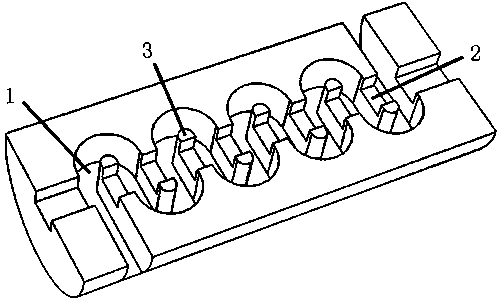
[0056] The invention relates to a micro-milling preparation method applied to a folded waveguide slow-wave structure, which is used for processing such as figure 1 The folded waveguide slow-wave structure shown. The slow wave structure is a semi-cylindrical body cut in the axial direction, and S-shaped grooves 1, straight grooves 2, and islands 3 formed by the intersection of the two are distributed on the axial section. The S-shaped grooves have a total of 75 periods, and the S-shaped grooves The aspect ratio is 255μm / 100μm, and the straight groove channel width is 140μm. The material of the slow wave structure is doped with Al with a volume fraction of 1.1% and a particle size of 50-100nm 2 o 3 The dispersed oxygen-free copper particles require that the dimensional accuracy after processing should be better than ±2μm, and the surface roughness Ra should be better than 60nm.

[0057] The micro-milling preparation process method of the present embodiment comprises the follo...

Embodiment 2

[0085] The structural parameters, operation method, workpiece material, required dimensional accuracy and surface roughness after processing are all the same in this embodiment and in Embodiment 1, the difference lies in:

[0086] In step 2, a Φ2.0mm hard alloy flat end milling cutter is used to mill the processing surface of the workpiece.

[0087] Step 6-1: Alternately process S-shaped grooves and straight grooves at the initial stage of processing. The selection range of processing parameters is: the spindle speed is 35000-40000r / min, the feed rate is 20-25μm / min, and the back cutting amount is 1-1.5 μm, using alcohol as lubricating coolant.

[0088] Step 6-2: After completing the processing of the straight groove in the depth direction, increase the cutting parameters to process the S-shaped groove with the remaining depth; the range of processing parameters is: the spindle speed is 45000-50000r / min, and the feed rate is 30- 35μm / min, back cutting amount is 2-3μm, using a...

Embodiment 3

[0091] The operating method, workpiece material, required dimensional accuracy and surface roughness after processing in this embodiment are the same as those in Embodiment 1, the differences are:

[0092] The aspect ratio of the S-shaped groove is 400 μm / 150 μm, and the channel width of the straight groove is 220 μm.

[0093] In step 2, a Φ2.0mm hard alloy flat end milling cutter is used to mill the processing surface of the workpiece.

[0094] Step 6-1: Alternately process S-shaped grooves and straight grooves at the initial stage of processing. The selection range of processing parameters is: the spindle speed is 40000-50000r / min, the feed rate is 25-35μm / min, and the back cutting amount is 1-2μm , Alcohol is used as lubricating coolant.

[0095] Step 6-2: After completing the processing of the straight groove in the depth direction, increase the cutting parameters to process the S-shaped groove with the remaining depth; the selection range of the processing parameters is:...


PUM

PropertyMeasurementUnit
Granularityaaaaaaaaaa

Abstract

The invention relates to a micro milling preparation process method applied to a folding waveguide slow wave structure. A clamp is used for installing and clamping a dispersion oxygen-free copper sample element; a milling cutter is used to eliminate an oxide scale on the surface of a material; a micro milling cutter for ultra-precise micro milling is installed into a cutter clamping mechanism of amain shaft; the cutter installing state is detected in real time through an in-site detection device; regulation is performed according to requirements; Z direction cutter alignment is performed on workpieces by using a CCD cutter alignment system; a special cutter alignment point is installed on the workpiece so that the cutter alignment point deviation existing after the cutter replacement is avoided; the processing stage is divided and the micro milling cutter walking track is planned to realize integral processing with a great depth-to-width ratio and a thin-wall complicated slow wave structure; finally, residue burs are removed by using an auxiliary process. The method realizes the ultra-precise micro milling process of the thin-wall complicated slow wave structure elements with themulti-period, and the great depth-to-width ratio; the dimension precision after the processing is superior to +/-2 mu m; the surface roughness degree Ra is superior to 60 nm.

Description

technical field [0001] The invention belongs to the field of ultra-precision micro-milling processing, and relates to a process method, in particular to a micro-milling preparation process method applied to a folded waveguide slow-wave structure. Background technique [0002] Terahertz waves have technical characteristics such as strong penetration, high safety, good orientation, and high bandwidth. They have great application prospects in the fields of national defense, deep space communication, remote imaging, security inspection, and medical diagnosis. The electric vacuum device based on the slow wave structure is the most potential solution to generate watt-level power output in the terahertz frequency band while realizing the miniaturization and economy of the terahertz radiation source. [0003] The slow wave structure is the core part of the electric vacuum device traveling wave tube amplifier. Such as figure 1 Shown is a folded waveguide slow-wave structure, which ...

Claims


Application Information

Patent Timeline
IPC IPC(8): B23C3/00B23Q3/06B81C99/00B82Y40/00
Inventor 吴春亚陈明君裴旭东王廷章韩鹏宇鲁义凡李曦光
Owner HARBIN INST OF TECH
Why Eureka
Try Eureka