
Split matching and testing device for coiled tubing well logging

A testing device and oil pipe technology, which is applied in the direction of measurement, drilling pipe, casing, etc., can solve the problems of increasing the fixing of electronic components and shortening the length, etc., and achieve the effect of firm use, increased fixing, and simple and reliable production

Active Publication Date: 2019-03-01
东营职业学院
View PDF5 Cites 0 Cited by
  • Summary
  • Abstract
  • Description
  • Claims
  • Application Information

AI Technical Summary

Problems solved by technology

[0003] The object of the present invention is to address the above-mentioned defects in the prior art, and to provide a split-coordinate testing device for coiled tubing well logging. Due to the split-type design, the production is simpler and more reliable, and there are no welding parts in the whole, avoiding the The heating of electronic components increases the fixing of electronic components at the same time, making the use of electronic components more firm and reliable; the length is also greatly shortened, which avoids the problem of disconnection of welding joints in inclined shafts

Method used


Image

  • Split matching and testing device for coiled tubing well logging
  • Split matching and testing device for coiled tubing well logging
  • Split matching and testing device for coiled tubing well logging

Examples


Embodiment 1

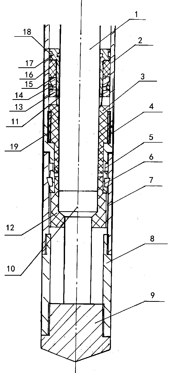
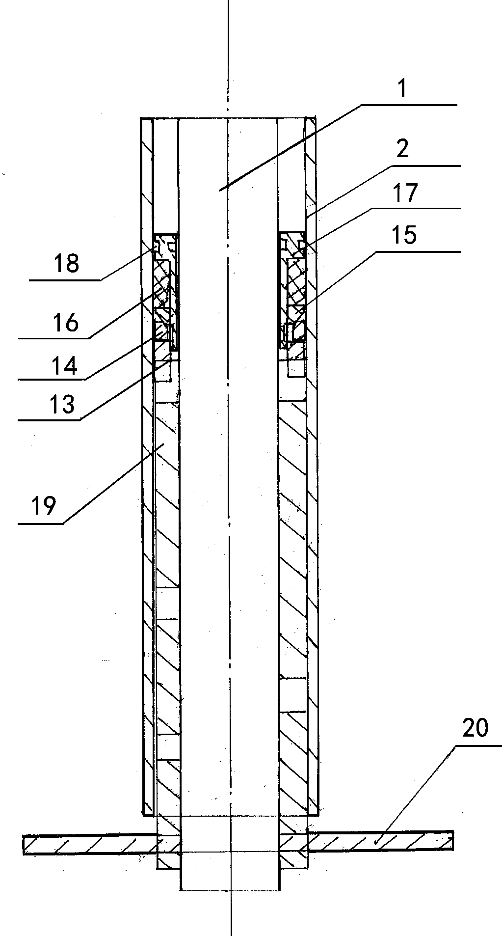
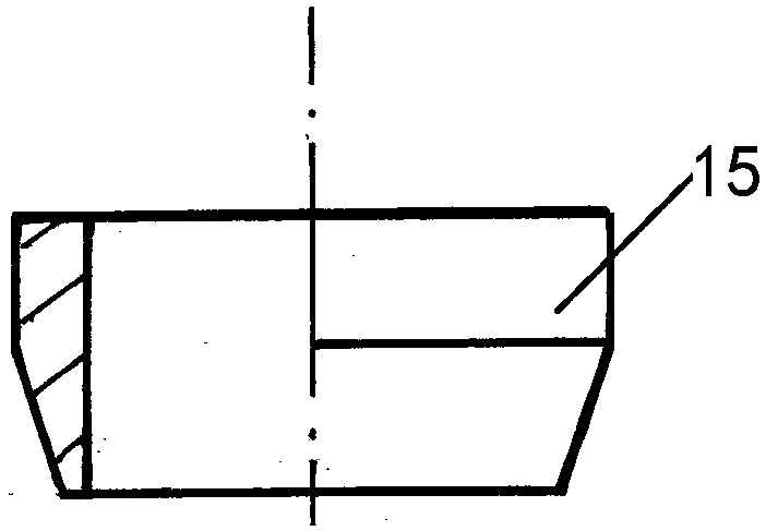
[0034] Embodiment 1, with reference to attached figure 1 , a coiled tubing logging split-coordinate testing device mentioned in the present invention, its technical scheme is: including sealing PTFE protection pad 3, transition joint 4, sealing rubber ring 5, split support ring 6, sealing protection sleeve 7 , test tube 8, guide shoe 9, test terminal 10, seat sealer 13, lock spring 14, cone 15, sealing rubber cylinder 16, liner 17, setting seal interference rubber ring 18, in coiled tubing 2 The cavity is pierced with a test cable 1, and at the end of the coiled tubing 2, a seat sealer 13, a lock spring 14, a cone 15, a sealing rubber tube 16 and a liner 17 are installed in the space between the coiled tubing 2 and the test cable 1. cavity, the seat sealer 13 is connected to the lower end of the liner 17, and then, refer to the attached figure 2 , align the seat sealer 13 with the seat seal wrench 20 and rotate, the liner 17 moves down, and the lock spring 14 drives the cone...

Embodiment 2

[0052] Embodiment 2, a coiled tubing logging split test device mentioned in the present invention, differs from Embodiment 1 in that: the cone and the lock spring are removed, and the seat sealer is changed to have ring teeth on the outer wall , the inner side is threaded with the lower end of the liner, and the ring teeth on the outer wall are fixed and supported by the coiled tubing. In this way, through the rotation of the special wrench for the seat seal, the upper surface of the seat seal is in contact with the sealing rubber cylinder 16 and squeezed Press the sealing rubber tube 16 to make it expand, thereby also realizing the long seal between the coiled tubing and the test cable.


PUM


Abstract

The invention relates to a split matching and testing device for coiled tubing well logging. According to the technical scheme, a setting machine is connected to the lower end of a liner tube, the setting machine is aligned and rotated through a setting wrench, the liner tube moves down, a locking spring drives a cone to move up, and a sealing cylinder is extruded to be expanded to realize the seal; a transition joint is connected to the lower end of a sealing tetrafluorohydrazine protective pad connected with a coiled tubing, a rubber ring and an open supporting ring are arranged on the lowerpart of the transition joint, a sealing protective sleeve is movably connected with the transition joint through the open supporting ring, a testing tube is connected with the tail end of a testing cable through a connecting and testing connector lug, and a guiding shoe is arranged at the lower end of the testing tube. The split matching and testing device for coiled tubing well logging has the beneficial effects that because of the split type design, the fabrication is more simple and reliable; no welding is achieved, the heating of electronic components is avoided, meanwhile, the fixation of the electronic components is increased, so that the use of the electronic components is stronger and more reliable; and compared with an original direct butt welding process, the phenomenon of fracture at a weld joint due to brittleness and hardness is overcome.

Description

technical field [0001] The invention relates to a coiled tubing logging auxiliary processing device and method, in particular to a coiled tubing logging split matching testing device. Background technique [0002] In the coiled tubing logging process, generally the logging joint is directly welded to the end of the coiled tubing, and then the testing instrument is connected and run downhole, but there is a problem that the measuring electronic Therefore, in welding, temperature control is a very important technical parameter, and this parameter has a specific numerical control method under the current technical conditions. At the same time, after the welding temperature is limited, the welding quality will be improved. It will be greatly affected; therefore, in actual operation, due to the fear of damage to electronic components during welding, the usual method is to lengthen the transition section, which creates a new problem: in a deviated well, if the well deviates If th...

Claims


Application Information

Patent Timeline
Patent Type & Authority Applications(China)
IPC IPC(8): E21B47/00E21B17/10
CPCE21B17/003E21B17/1042E21B47/01H02G15/18
Inventor 周连兵孙艳玲张云鹏
Owner 东营职业学院
Learn More