Large pipeline structure

A pipeline and large-scale technology, applied in the direction of large containers, pipeline protection, superstructure sub-assembly, etc., can solve the problems of weak welding between the honeycomb core and the upper and lower panels, unstable overall structure, poor impact resistance, etc., and achieve the assembly cycle short, maintain structural integrity, and have a long service life

Inactive Publication Date: 2019-03-01
张跃
View PDF5 Cites 0 Cited by
  • Summary
  • Abstract
  • Description
  • Claims
  • Application Information

AI Technical Summary

Problems solved by technology

However, the honeycomb core is connected into one body through multiple honeycomb structures, and the upper and lower ends of the honeycomb core are in line contact with the upper and lower panels. During the brazing process, the welding between the honeycomb core and the upper and lower panels will be weak, and gaps will easily occur. Or voids, etc., which will lead to instability of the overall structure, low strength, poor impact resistance, etc.

Method used


Image

  • Large pipeline structure
  • Large pipeline structure
  • Large pipeline structure

Examples


Embodiment 1

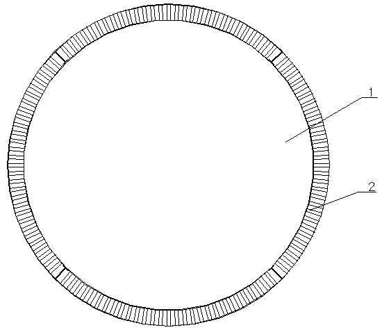
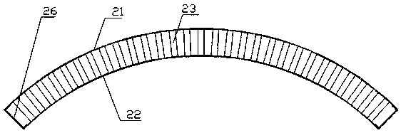
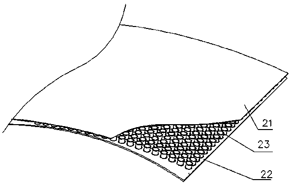
[0052] Such as Figure 1~Figure 5 As shown: a large-scale pipeline structure, including a pipeline body 1, which is composed of a plurality of metal plates 2 spliced ​​together. The metal plate 2 comprises a first panel 21, a second panel 22 and a plurality of hollow tubes 23 arranged between the first panel 21 and the second panel 22, and a hollow tube 23 is arranged between the first panel 21 and the second panel 22. There is a brazing layer; the two ends of the hollow tube 23 are provided with flanging 25, which is turned out into a circular structure. The flanging 25 of the hollow tube is connected to the first panel 21 and the second panel 22 by soldering 24 .

[0053] Both the first panel 21 and the second panel 22 are curved panels. The two ends of the hollow tube 23 are vertically connected with the contact surface of the panel. The linetype of curved panels is arc. A plurality of hollow tubes 23 are arranged at intervals, and the axis of each hollow tube 23 is per...

Embodiment 2

[0060] Such as Figure 6 Shown: the difference with embodiment 1 is that the pipe body 1' is formed by splicing a plurality of metal plates 2'. Both the first panel 21' and the second panel 22' are plane plates, and the plane plates are cuboid plates. A plurality of metal plates 2' are spliced ​​to form a rectangular parallelepiped pipeline.

[0061] Other structures are with embodiment 1.

Embodiment 3

[0063] The difference from Embodiment 1 is that the pipe body is composed of a plurality of metal plates spliced ​​together. The first panel is an arc-shaped curved panel, the second panel is a flat panel, the flanging at one end of the hollow tube is parallel to the flat panel, and the flanging at the other end is an inclined surface, which is parallel to the contact surface of the curved panel, so that when When the hollow tube is connected to the two panels, there is no gap.

[0064] A plurality of metal plates are spliced ​​to form a pipe with a circular cross-section of the outer ring and a square cross-section of the inner ring.

[0065] Other structures are with embodiment 1.


PUM


Abstract

The invention discloses a large pipeline structure. The large pipeline structure comprises a pipeline body, wherein the pipeline body is formed by splicing at least two metal plates, each metal platecomprises a first panel, a second panel and a plurality of hollow pipes arranged between the first panel and the second panel, connecting layers are arranged between the hollow pipes and the first panels and between the hollow pipes and the second panels, and flanges are arranged at least one ends of the hollow pipes. The large pipeline structure has the advantages of light dead weight, high strength, stable structure, sound insulation as well as noise reduction, heat preservation, high temperature resistance, vibration resistance, long service life and the like; and the pipeline body of the large pipeline structure can be a gas delivery pipeline, an oil delivery pipeline, a water supply and drainage pipeline, a vacuum transportation pipeline and the like.

Description

technical field [0001] The invention relates to a pipeline structure, especially a large pipeline structure. Background technique [0002] Existing pipeline materials mainly include steel pipes (such as welded steel pipes, seamless steel pipes), cast iron pipes (such as gray pipes, ductile iron pipes), concrete pipes, plastic pipes and composite pipes, etc. However, these pipes need to be processed through their outer walls. In order to have certain anti-corrosion, moisture-proof, anti-seepage and other properties. [0003] In addition, the above-mentioned pipelines all have certain defects. First, steel pipes, cast iron pipes and concrete pipes are heavy, especially large pipes, which are time-consuming and labor-intensive; second, the production cycle is long; third, the compression resistance is poor; fourth, the insulation effect is poor; Fifth, poor vibration resistance; sixth, poor heat preservation effect. [0004] There are also pipes made of honeycomb panels. The...

Claims


Application Information

Patent Timeline
Patent Type & Authority Applications(China)
IPC IPC(8): F16L9/21F16L59/02
CPCA45C5/02A45C5/045A45C5/14A45C13/001A45C13/04A45C13/36A47B13/08A47B96/02A47B96/206A47B2220/008A47C7/00B32B1/00B32B3/08B32B3/085B32B3/12B32B3/20B32B3/266B32B7/08B32B15/01B32B15/011B32B15/012B32B15/013B32B15/015B32B15/017B32B15/18B32B15/20B32B2250/40B32B2307/102B32B2307/304B32B2307/306B32B2307/3065B32B2307/50B32B2307/558B32B2307/714B32B2307/718B32B2419/00B32B2439/00B32B2479/00B32B2605/08B32B2605/10B32B2605/12B32B2605/18B62D25/00B62D27/02B62D29/00B63B3/26B63B3/48B63B3/56B64C1/12B64C2001/0081B65D81/3818B65D90/028E01B1/002E01B2204/09E01D19/02E01D19/083E01D19/125E01D2101/30E06B3/7015E06B2003/7049E21D9/14E21D11/155E21D11/18F16L9/21F16L59/02
Inventor 张跃
Owner 张跃
Why Eureka
Try Eureka