
Production method for (METH)acrylic acid or ester thereof

A manufacturing method and technology of acrylic acid, applied in the direction of carboxylate preparation, separation methods, chemical instruments and methods, etc., can solve the problems of high polymerizability, low density, device blockage, etc., achieve long-term stable continuous production, and prevent polymer failure Generated and stacked effects

Active Publication Date: 2019-03-01
MITSUBISHI CHEM CORP
View PDF12 Cites 2 Cited by
  • Summary
  • Abstract
  • Description
  • Claims
  • Application Information

AI Technical Summary

Problems solved by technology

However, the vapor pressure of most of the polymerization inhibitors is lower than that of (meth)acrylic acid, and in most cases, the added polymerization inhibitor is hardly included in the volatilized gas of (meth)acrylic acid
It is believed that even if no polymerization inhibitor is contained, the (meth)acrylic acid in a gaseous state has a low density so that polymerization does not substantially occur, but once the gas is condensed to form a condensate, the condensate has Due to high polymerization, clogging of devices, etc.

Method used

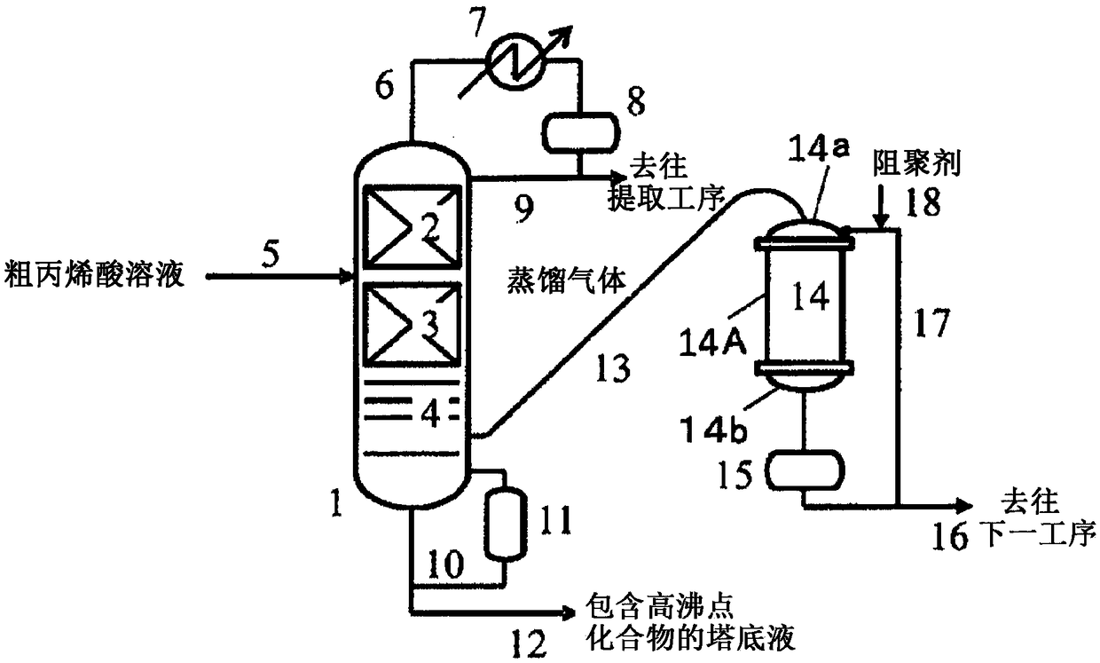
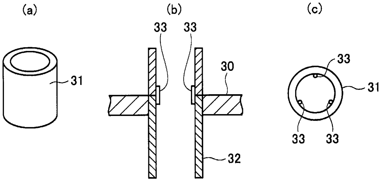

Image

  • Production method for (METH)acrylic acid or ester thereof
  • Production method for (METH)acrylic acid or ester thereof
  • Production method for (METH)acrylic acid or ester thereof

Examples


Embodiment

[0073] The present invention will be described in more detail through examples below, but the present invention is not limited by the following examples. In addition, the following examples and comparative examples were carried out using test equipment, but the dimensions of each part are different from those of the actual machine.

[0074] For convenience of description, a comparative example will be given first.

Embodiment 1

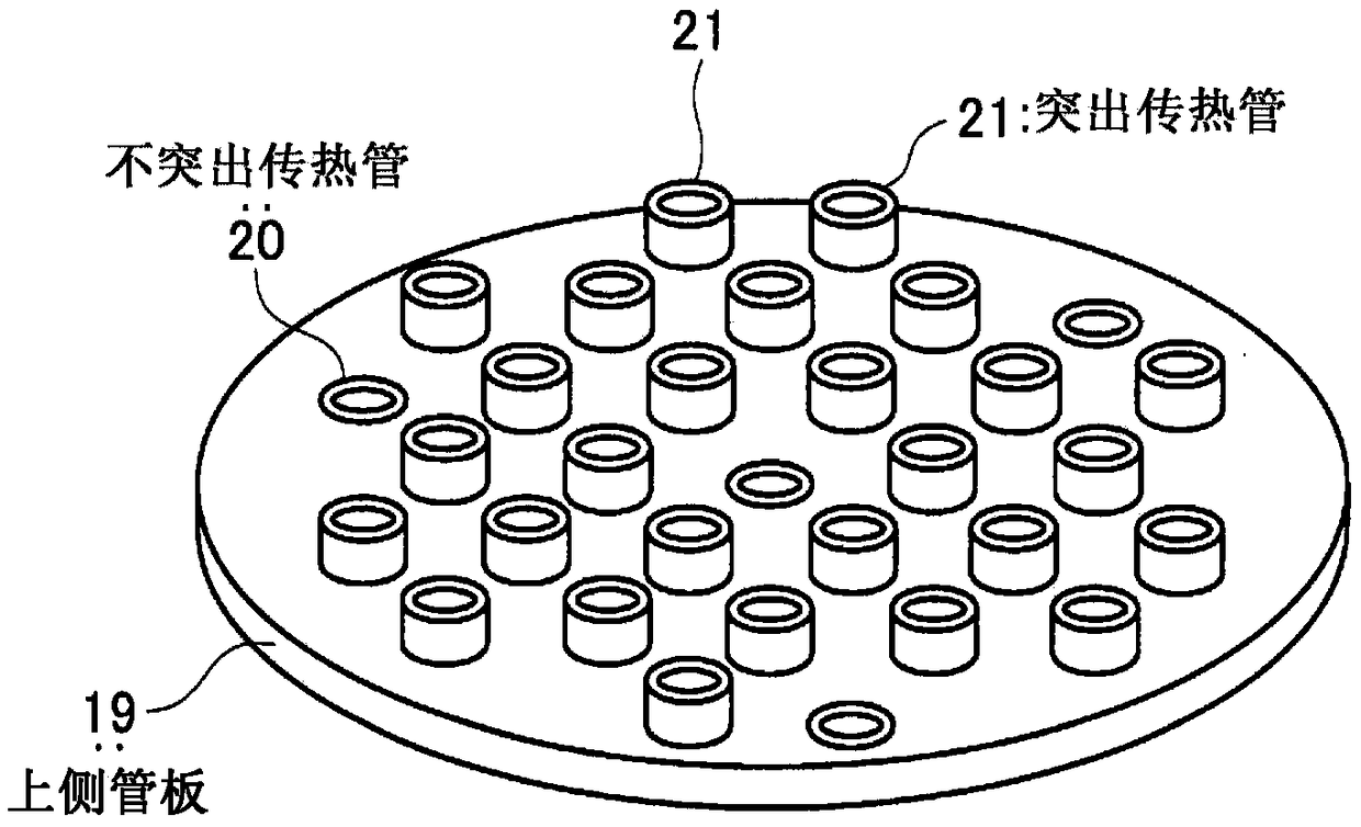
[0086] Operation was performed under the same conditions as those of Comparative Example 3 except that only one central part of the short tubes welded to the heat transfer tubes was removed. In this state, only the center one of the heat transfer tubes does not protrude, and the other 18 protrude by 10 mm. As a result, almost no captured matter was seen in the filter even after the 3-day operation. As a result of checking after washing with water, only a few lumps of polymer were confirmed on the outer peripheral portion of the upper tube sheet surface.

Embodiment 2

[0088] Further, three short tubes at the position symmetrical to the upper tube sheet surface among the short tubes near the outermost peripheral portion were removed, and the operation was carried out for 3 days under the same conditions as in Example 1. In this state, one of the heat transfer tubes in the center and three (4 in total) at equidistant positions on the outer periphery do not protrude from the heat transfer tube, and the other 15 protrude by 10 mm. During the operation period, no trapped matter was confirmed in the filter except for the dust that was considered to be mixed when it was opened. After washing with water, polymer lumps were not confirmed, and when all the short tubes were removed, streaks due to dirt were observed in about half of the joints of the short tubes.


PUM

PropertyMeasurementUnit
areaaaaaaaaaaa

Abstract

The method comprises steps of: using a vertical multi-tubular heat exchanger having a tubular body, an upper side tube plate and a lower side tube plate disposed on the upper extremity side and the lower extremity side of the tubular body respectively, a plurality of heat-transfer tubes erected between the upper-side tube plate and the lower-side tube plate, and lid parts each disposed on the upper side of the upper-side tube plate and the lower side of the lower-side tube plate, the upper-side tube plate and the lid part forming a receiving chamber whereinto a distillation gas is introduced,which is then cooled while passing through the interior of the heat-transfer tubes and turned into a condensation solution; and introducing into the receiving chamber a solution containing a polymerization inhibitor. Some of the plurality of heat-transfer tubes have upper ends thereof protruding above the upper-side tube plate while the rest are non-protruding. The solution containing the polymerization inhibitor, which has come in contact with the distillation gas inside the receiving chamber, forms a liquid-flow layer of a predetermined liquid depth above the upper side tube plate.

Description

technical field [0001] The present invention relates to a method for producing (meth)acrylic acid or its ester (hereinafter sometimes referred to as "(meth)acrylic acid"). Specifically, the present invention relates to a method for producing (meth)acrylic acid, which It includes the process of turning the treatment liquid containing (meth)acrylic acid into a distillation gas by a distillation tower, and turning the distillation gas into a condensate by using a vertical shell-and-tube heat exchanger. This method can prevent the vertical shell-and-tube heat exchanger from The formation and accumulation of polymers in the exchanger enables continuous production of (meth)acrylic acid in a long-term stable manner. [0002] In addition, in this specification, (meth)acrylic acid is the generic term of acrylic acid and methacrylic acid, and it may be either one of these, and may be both. In addition, (meth)acrylic acid may be only any one of (meth)acrylic acid and (meth)acrylate, and...

Claims


Application Information

Patent Timeline
Patent Type & Authority Applications(China)
IPC IPC(8): C07C51/44C07C57/075F28D7/16F28F9/22F28F19/00
CPCF28F9/22F28F19/00F28D7/16C07C51/44C07C57/04B01D5/00F28F9/013B01D3/007B01D3/14C07C67/54C07C69/54
Inventor 小川宁之
Owner MITSUBISHI CHEM CORP
Learn More