
Container valve for driving gas cylinder set of carbon dioxide fire extinguishing system

A fire-extinguishing system and driving gas technology, applied in fire rescue and other directions, can solve problems such as pressure relief, system paralysis, time-consuming and labor-intensive

Active Publication Date: 2019-03-08
CHINA NON-FERROUS METALS PROCESSING TECH CO LTD
View PDF9 Cites 0 Cited by
  • Summary
  • Abstract
  • Description
  • Claims
  • Application Information

AI Technical Summary

Problems solved by technology

[0004] In the actual production process, the nitrogen filled in the driving gas bottle set contains impurities and moisture. After a long period of corrosion, the inner wall of the driving gas bottle set container is rusted, and the container valve opened during fire extinguishing (or testing) is damaged due to The impact of rusty particles produces scratches, and impurities adhere to the sealing parts, resulting in lax closure of the container valve and pressure relief. It will lead to system paralysis, cause immeasurable losses to the rolling system, and bring danger to the lives of personnel
[0005] In addition, in order to ensure that the pressure of the driving gas cylinder group of the fire extinguishing system is always in a safe area, the operator needs to regularly check the pressure of the pressure gauge of the driving gas cylinder group visually. Nitrogen is added to the gas bottle group to ensure the stability and reliability of the system, so the frequency is high, time-consuming and labor-intensive

Method used


Image

  • Container valve for driving gas cylinder set of carbon dioxide fire extinguishing system
  • Container valve for driving gas cylinder set of carbon dioxide fire extinguishing system
  • Container valve for driving gas cylinder set of carbon dioxide fire extinguishing system

Examples


Embodiment Construction

[0017] The technical solution of the present invention will be described in further detail below in conjunction with the accompanying drawings and embodiments.

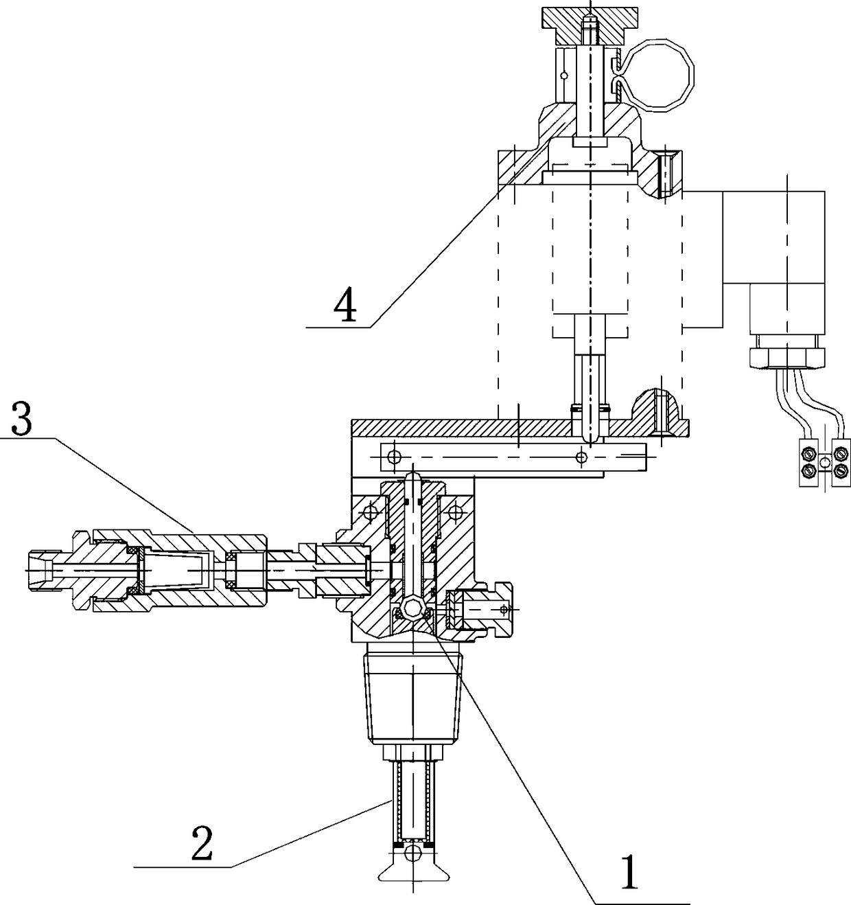
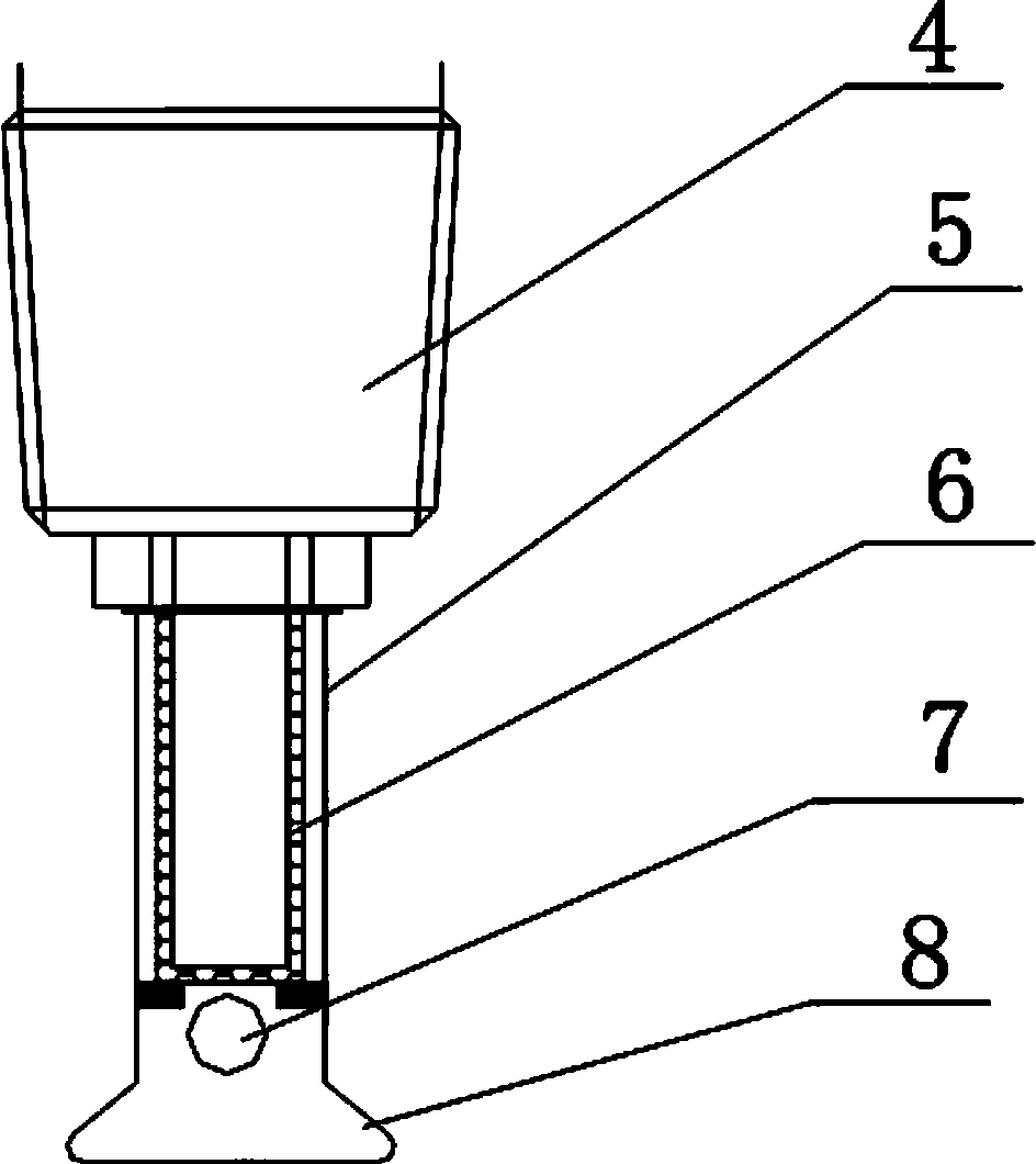
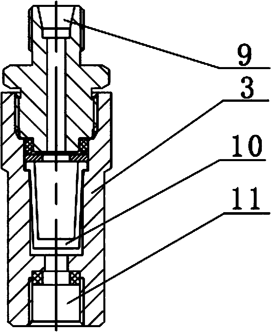
[0018] Such as figure 1 , 2 As shown in , 3 and 4, the container valve for the driving gas bottle set of the carbon dioxide fire extinguishing system includes a container valve body 4, an anti-clogging component 2 is installed at the bottom of the container valve body, the anti-clogging component includes a housing 5, and the upper end of the housing is open And the interior is a cavity, the shell is threadedly connected to the bottom of the container valve body, and a cylindrical filter element 6 is built in. The cylindrical filter element is a sintered filter element of copper powder particles. Located below the cylindrical filter element, the end of the shell is a conical tail 8, and the bottom of the conical tail is closed; a filter 3 is threaded between the container valve inlet 11 and the inflation port 9 of th...


PUM


Abstract

The invention discloses a container valve for a driving gas cylinder set of a carbon dioxide fire extinguishing system. The container valve comprises a container valve body. An anti-blockage componentis mounted at the bottom of the container valve body and comprises a shell. An opening is formed in the upper end of the shell, a cavity is formed in the shell, and a cylindrical filter element is arranged in the shell. Multiple gas release holes distributed at equal distances are formed in the lower portion of the shell, and the gas release holes are located below the cylindrical filter element.The tail end of the shell is a conic tail, and the bottom end of the conic tail is sealed. A filter is mounted between an inlet of the container valve and an inflation connector of a nitrogen sourcebottle. A threaded connector on the container valve body is in threaded connection with an electro connecting pressure gauge, and the electro connecting pressure gauge is connected with a fire extinguishing automatic alarm control cabinet through a wire. According to the container valve, the function of rapidly, safely and effectively solving valve element replacement is achieved, the reliabilityof the carbon dioxide fire extinguishing system of roll equipment is improved, and a convoy function is achieved on safe and reliable operation of the carbon dioxide fire extinguishing system of a roll.

Description

technical field [0001] The invention relates to the technical field of fire-fighting equipment for non-ferrous metal processing, in particular to a container valve for a driving gas bottle group of a carbon dioxide fire-extinguishing system, which is used in fire-extinguishing equipment for stainless steel and non-ferrous metal processing rolling mills. Background technique [0002] The main component of process lubricant used in the production process of stainless steel, copper, aluminum and other metal strip cold rolling mills is kerosene, which produces a large amount of oil mist during the rolling process, which is easily ignited due to mechanical overheating, static electricity, broken strips, etc. If a fire is caused, the fire extinguishing button (or the detector is automatically activated) should be activated in time to open the container valve of the driving gas cylinder group, and then the driving gas will open the selection valve and the container valve of the fire...

Claims


Application Information

Patent Timeline
Patent Type & Authority Applications(China)
IPC IPC(8): A62C13/64A62C37/11
CPCA62C13/64A62C37/11
Inventor 吴存福王光林石磊胡建春白峰张伟星梁彦峰刘周同李垒高朝阳杨义普崔婧
Owner CHINA NON-FERROUS METALS PROCESSING TECH CO LTD
Learn More