
Distributed utilization method and utilization system of coking waste heat

A distributed and waste heat technology, used in the heating of coke ovens, coke ovens, coke oven parts, etc., can solve the problems of polluted waste water, low energy efficiency condensation waste water, etc., achieve high energy efficiency utilization rate, improve utilization cleanliness, avoid The effect of wastewater

Pending Publication Date: 2019-03-08
JINAN METALLURGICAL CHEM EQUIP CO LTD
View PDF2 Cites 0 Cited by
  • Summary
  • Abstract
  • Description
  • Claims
  • Application Information

AI Technical Summary

Problems solved by technology

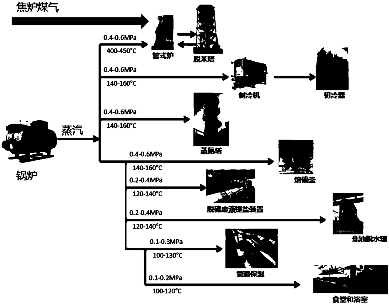
[0004] Therefore, research and development of a clean, low-carbon waste heat recovery process and method overcomes the existing coking waste heat utilization process that directly converts waste heat energy into steam, which has low energy efficiency and produces a large amount of condensed waste water during steam use, and In the process steps of benzene removal and ammonia distillation, the problem of a large amount of polluted wastewater has become very necessary and urgent

Method used


Image

  • Distributed utilization method and utilization system of coking waste heat
  • Distributed utilization method and utilization system of coking waste heat
  • Distributed utilization method and utilization system of coking waste heat

Examples


Embodiment 1

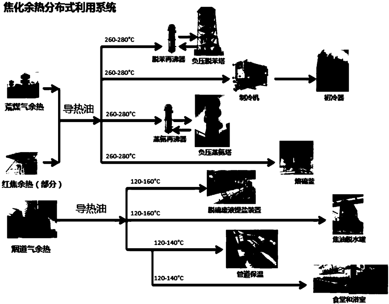
[0064] A method for distributed utilization of coking waste heat. The method includes the following steps: first convert the coking waste heat into gas, install a heat exchanger on the waste heat gas pipeline, and then make the heat transfer oil enter the heat exchanger to absorb the heat in the waste heat gas The heat transfer oil A is obtained, and the heat transfer oil A is supplied to the waste heat utilization equipment through the pipeline to obtain the used heat transfer oil B, and then the heat transfer oil B is returned to the heat exchanger through the pipeline for recycling.

[0065] The above method first converts the coking waste heat into gas, and installs a heat exchanger on the waste heat gas pipeline, and then makes the heat transfer oil enter the heat exchanger to absorb the heat in the waste heat gas to obtain heat transfer oil A, and supply heat transfer oil A to the waste heat through the pipeline Use the equipment to obtain the used heat transfer oil B, and t...

Embodiment 2

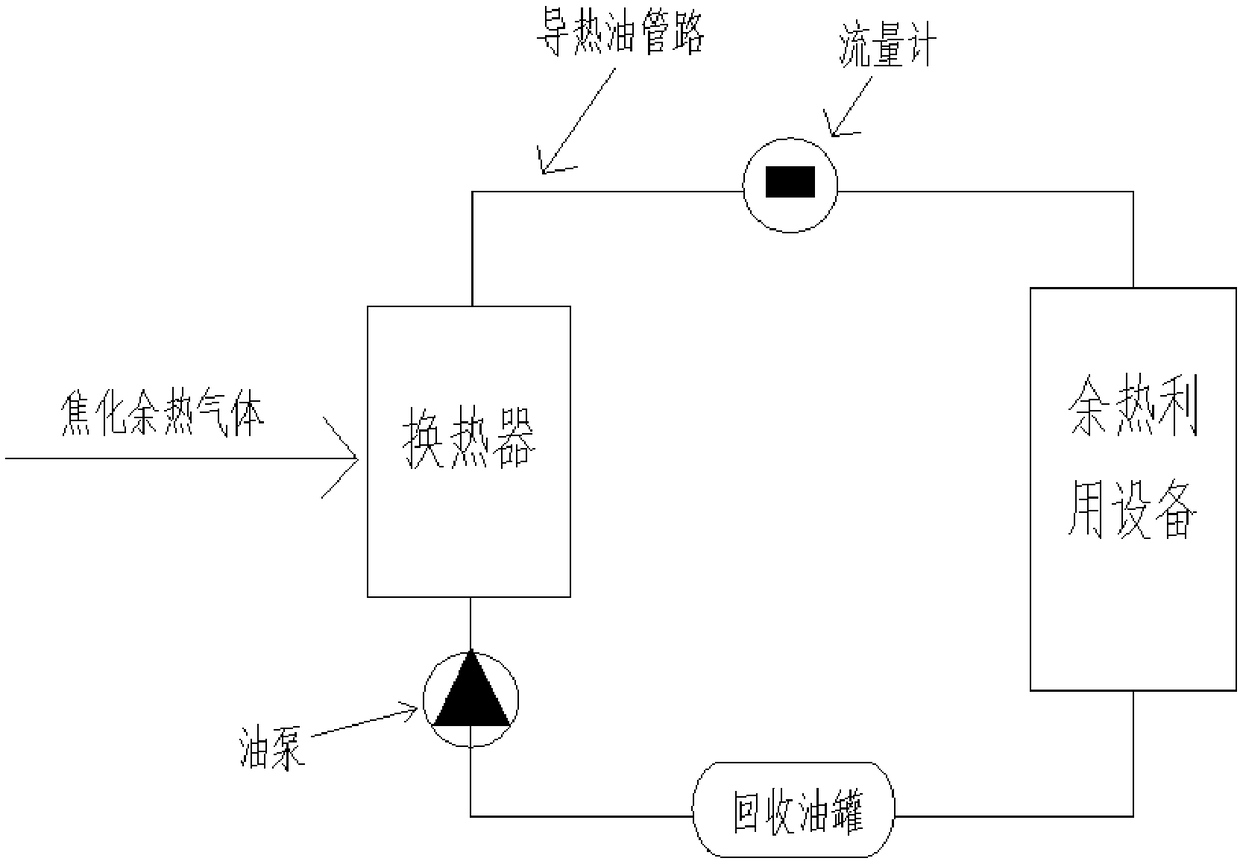
[0083] Such as image 3 As shown, a distributed utilization system of coking waste heat includes a heat conduction oil pipeline, an oil pump, a flow meter, a heat exchanger, waste heat utilization equipment, and a recovery oil tank; the oil pump, flow meter, exchange The heat exchanger, the waste heat utilization equipment and the recovery oil tank are cyclically connected in turn through the heat transfer oil pipeline.

[0084] The distributed utilization system of coking waste heat provided by the present invention includes heat conduction oil pipelines, oil pumps, flow meters, heat exchangers, waste heat utilization equipment and recovery oil tanks; the aforementioned distributed utilization system of coking waste heat uses oil pumps , Flowmeter, heat exchanger, waste heat utilization equipment and recovery oil tank are connected in turn through the heat transfer oil pipeline. The closed operation of the conductive oil in the utilization system not only improves the energy eff...


PUM


Abstract

The invention provides a distributed utilization method and a utilization system of coking waste heat, and relates to the technical field of waste heat utilization in the coking industry. The distributed utilization method of the coking waste heat comprises the following steps: firstly, converting the coking waste heat into gas and installing a heat exchanger on a waste heat gas pipeline; then enabling heat conduction oil to enter the heat exchanger for absorbing the heat in the waste heat gas to obtain heat conduction oil A; supplying the heat conduction oil A to waste heat utilizing equipment through a pipeline to obtain utilized heat conduction oil B; then feeding back the heat conduction oil B to the heat exchanger through the pipeline for recycling. Compared with a traditional methodof directly conversing the coking waste heat into steam for utilizing, the distributed utilization method of the coking waste heat has the advantages of cleanness, low carbon and high energy efficiency utilization rate; in addition, the production of a large amount of wastewater in the waste heat utilization process is also avoided, so that the utilization cleanliness of coking waste heat energy is greatly improved.

Description

Technical field [0001] The invention relates to the technical field of amateur heat utilization of coking chemical industry, in particular to a distributed utilization method and utilization system of coking waste heat. Background technique [0002] The coking industry is not only an important energy production sector, but also a high energy consumption and high pollution industry. In the processing process of the coking industry, as far as the heat from the coke oven product is concerned, a large amount of waste heat of raw gas, red coke and flue gas will be brought out. The recovery of these waste heat plays a very important role in saving energy, reducing consumption and improving economic benefits in coking plants. The existing technologies for the utilization of waste heat from raw gas, red coke and flue gas are generally based on the idea of ​​recycling these waste heat energy through inert gas circulation to recover sensible heat, and then converting it into high-temperat...

Claims


Application Information

Patent Timeline
Patent Type & Authority Applications(China)
IPC IPC(8): C10B27/00C10B29/00
CPCC10B27/00C10B29/00Y02P20/129
Inventor 汤志刚王登富温燕明王光华姜爱国康春清刘同清陈善龙李桂花孙兆俊
Owner JINAN METALLURGICAL CHEM EQUIP CO LTD
Learn More