
Metal foil type strain gauge design and manufacturing method based on hybrid 3D printing technology

A 3D printing and manufacturing method technology, applied in the field of additive manufacturing, can solve the problems of limited electrical conductivity, difficult to meet, and low mechanical strength

Active Publication Date: 2019-03-08
SOUTHEAST UNIV
View PDF7 Cites 2 Cited by
  • Summary
  • Abstract
  • Description
  • Claims
  • Application Information

AI Technical Summary

Problems solved by technology

However, it is difficult to meet the demand for customized strain gauges in consumer electronics, aerospace, automotive industry, defense industry and other fields
3D printing technology is very suitable for small batch and customized production of electronic products. However, conductive ink is generally used to make conductive lines at present, which has low mechanical strength and limited conductive performance.

Method used


Image

  • Metal foil type strain gauge design and manufacturing method based on hybrid 3D printing technology
  • Metal foil type strain gauge design and manufacturing method based on hybrid 3D printing technology
  • Metal foil type strain gauge design and manufacturing method based on hybrid 3D printing technology

Examples


Embodiment 1

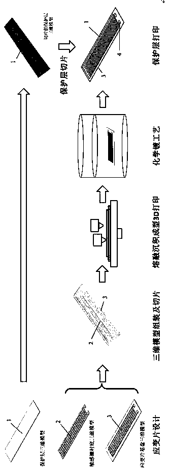
[0028] Embodiment 1: see Figure 1-Figure 5 , a metal foil strain gauge design and manufacturing method based on hybrid 3D printing technology, the method is as follows:

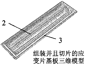
[0029] 1) Three-dimensional model design of the strain gauge substrate, sensitive grid substrate and protective layer: the geometry and properties of the substrate, sensitive grid substrate and protective layer are defined in the application of computer-aided design software, and the information generated by the computer has a sense of reality The visual 3D model can be exported to the STL file format, which uses triangular meshes to express the shape of the outer contour of the object. It is a 3D graphics file format that serves 3D printing manufacturing technology.

[0030] 2) Slicing of the 3D model of the strain gauge base plate and sensitive grid substrate: Import the 3D model of the metal foil strain gauge base plate and sensitive grid substrate into the 3D printing slicing software, set the nozzle tempe...

Embodiment 2

[0040] Example 2: see figure 1 — Figure 5 , a metal foil strain gauge design and manufacturing method based on hybrid 3D printing technology, the method is as follows:

[0041] 1) Three-dimensional model design of the strain gauge substrate, sensitive grid substrate and protective layer: the geometry and properties of the substrate, sensitive grid substrate and protective layer are defined in the application of computer-aided design software, and the information generated by the computer has a sense of reality The visual 3D model can be exported to the STL file format, which uses triangular meshes to express the shape of the outer contour of the object. It is a 3D graphics file format that serves 3D printing manufacturing technology.

[0042] 2) Slicing of the 3D model of the strain gauge base plate and sensitive grid substrate: Import the 3D model of the metal foil strain gauge base plate and sensitive grid substrate into the 3D printing slicing software, set the nozzle tem...


PUM


Abstract

The invention relates to a metal foil type strain gauge design and manufacturing method based on a hybrid 3D printing technology. Three-dimensional models of a strain gauge base disc, a sensitive gridbacking and a protective layer are designed by adopting computer-aided design software; a 3D printing slicing software is used for assembling the base disc model and the sensitive grid backing model,slicing processing is carried out according to printing parameters so as to obtain numerical control programming language codes to drive a fused deposition forming 3D printer to manufacture a straingauge base plate, the base disc is made of a non-platable plastic, and the sensitive grid backing is printed by adopting a platable plastic; a metal or an alloy layer is deposited on the surface of the platable plastic by using a chemical plating process; a numerical control programming language code is obtained through slicing the protective layer model, the protective layer is printed on the surface of a sensitive grid by utilizing the fused deposition forming 3D printer, and thus a metal foil type strain gauge is manufactured. According to the design and the manufacturing method, the designand manufacturing process of the metal foil type strain gauge is simplified, the conductive performance and the mechanical strength of the sensitive grid are improved, and the production requirementsof the small-batch and customized metal foil type strain gauges can be met.

Description

technical field [0001] The invention relates to a metal foil strain gauge design and manufacturing technology, which belongs to the technical field of additive manufacturing. Background technique [0002] The resistance strain gauge is a sensitive device that converts the strain change on the measured object into an electrical signal. Metal foil strain gauges are one of the most widely used resistance strain gauges. This type of strain gauge is usually made of metal and alloy films deposited on the polymer film substrate by evaporation or sputtering, and then the metal / alloy thin layer is patterned by photolithography to form a sensitive gate, and finally covered with a layer of protection. In actual use, the strain gauge is tightly bonded to the substrate that generates mechanical strain with an adhesive. When the substrate is stressed and the stress changes, the resistance strain gauge also deforms together, so that the resistance value of the sensitive grid of the strai...

Claims


Application Information

Patent Timeline
IPC IPC(8): C23C18/24C23C18/30C23C18/32C23C18/40G01B7/16B29C64/118B33Y80/00
CPCB33Y80/00B29C64/118C23C18/24C23C18/30C23C18/32C23C18/40G01B7/18
Inventor 李霁汪杨何江玲向耿召刘瀚达
Owner SOUTHEAST UNIV
Learn More