Detachable split efficient compressor air cylinder base and assembling method thereof

A technology for compressors and cylinder blocks, applied in the field of refrigeration compressors, can solve the problems of uneven chamfering or chamfering flanging, reduced refrigeration capacity of compressors, stuck compressor pistons, etc. The effect of flexibility and high positioning accuracy

Pending Publication Date: 2019-03-08
WUHU ABAUR MECHANICAL & ELECTRICAL
View PDF0 Cites 1 Cited by
  • Summary
  • Abstract
  • Description
  • Claims
  • Application Information

AI Technical Summary

Problems solved by technology

However, as far as the overall performance of the compressor is concerned, the crescent groove has no practical significance except for the assembly of the piston pin and connecting rod; at the same time, due to the existence of the crescent groove, it is necessary to set chamfers around the crescent groove. Uneven corners or chamfering and flanging are very likely to cause the compressor piston to get stuck, resulting in the failure of the entire compressor; what's more, the existence of this crescent groove will cause the compressor refrigeration oil to be pulled to the top of the short shaft of the crankshaft by centrifugal force. During the splash lubrication process, it becomes an important channel for the refrigerating machine oil to enter the refrigeration system. When the refrigerant enters the evaporator and condenser of the refrigeration system, it will occupy a part of the volume and affect the heat transfer. Because the refrigerant is mixed with oil, the refrigerant participating in the refrigeration cycle The reduction of purity and cooling capacity per unit mass leads to a decrease in compressor cooling capacity and COP value, which is obviously inconsistent with the concept of high efficiency, energy saving and environmental protection advocated by the society.

Method used


Image

  • Detachable split efficient compressor air cylinder base and assembling method thereof
  • Detachable split efficient compressor air cylinder base and assembling method thereof
  • Detachable split efficient compressor air cylinder base and assembling method thereof

Examples


Embodiment 1

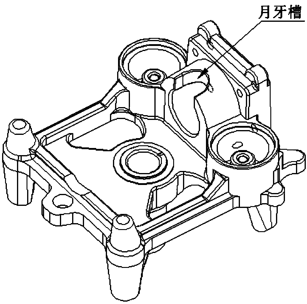
[0038] Such as Figure 2 to Figure 5 The expressed structure of the present invention is a detachable split high-efficiency compressor cylinder block, including a lower base 8 . In order to overcome the deficiencies and existing problems of the prior art, realize the invention purpose of overcoming the hidden danger of the piston of the compressor and improving the refrigeration efficiency of the compressor, the technical scheme adopted by the present invention is as follows:

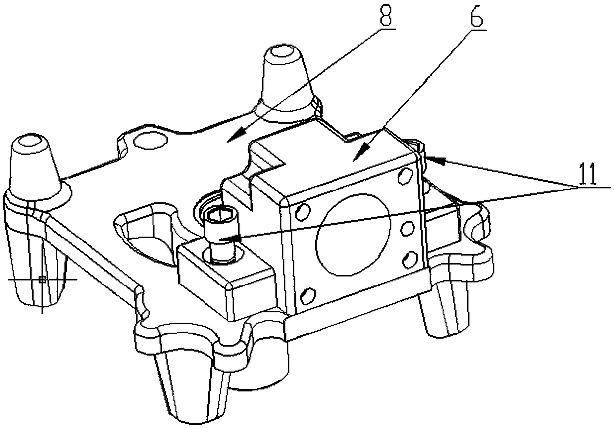
[0039] The cylinder block of the detachable split high-efficiency compressor of the present invention is provided with an upper cylinder body 6, and the upper cylinder body 6 is fastened and connected to the lower base 8 by fastening screws 11 for the upper cylinder body.

[0040] In the detachable split-type high-efficiency compressor of the present invention, the split detachable cylinder block includes the upper cylinder block 6 and the lower base 8; the cylinder block technology can reduce the hidde...

Embodiment 2

[0047] Embodiment two, such as Figure 6 to Figure 8 Shown:

[0048] The present invention provides a detachable split high-efficiency compressor cylinder block, including a first-stage noise reduction lower base 16, the cylinder block is provided with a first-stage noise reduction upper cylinder body 14, and the first-stage noise reduction upper cylinder body 14 The fastening screw 11 of the upper cylinder body is accurately positioned and fastened to the lower base 16 of the first-level noise reduction; the first-level noise reduction chamber 17 and the first-level noise reduction chamber 17 are respectively arranged on both sides of the upper cylinder body 14 of the first-level noise reduction. Mholtz resonator.

[0049] One side of the first-stage anechoic chamber 17 is fastened with the coil pipe of the resistant anechoic chamber by screws.

[0050] The first-stage muffler upper cylinder 14 is provided with an exhaust muffler and a Helmertz exhaust resonant cavity respe...

Embodiment 3

[0054] Embodiment three, such as Figure 9 , Figure 10 Shown:

[0055] The present invention provides a detachable split high-efficiency compressor cylinder block, including a lower base 8, the cylinder block is provided with an upper cylinder body 6, and the second-stage noise reduction upper cylinder body 20 is fastened with screws through the upper cylinder body 11 is fastened to the lower base 8; the primary anechoic chamber 21 and the secondary anechoic chamber 22 are arranged on the same side of the secondary anechoic upper cylinder 20.

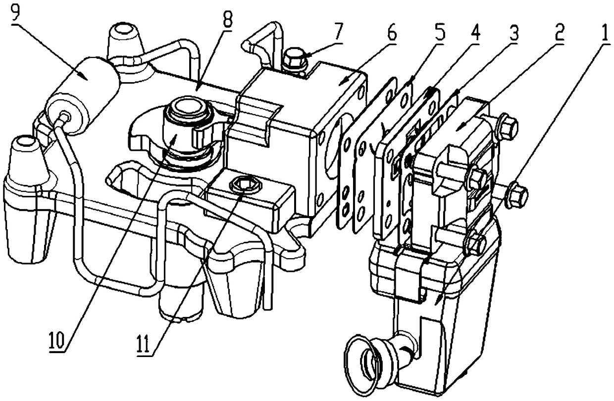
[0056] The cylinder head 2 of the high-efficiency compressor is connected to the upper cylinder body 6 through the sequentially arranged cylinder head gasket 3, valve plate assembly 4, suction valve plate 5, and valve plate gasket.

[0057] The high-efficiency compressor is provided with a suction muffler 1; the suction muffler 1 is installed on the suction limit side of the cylinder head 2.

[0058] The secondary anechoic chamber 2...


PUM


Abstract

The invention discloses a detachable split efficient compressor air cylinder base. The detachable split efficient compressor air cylinder base comprises a lower base (8). The air cylinder base is provided with an upper cylinder body (6). The upper cylinder body (6) is in fastened connection to the lower base (8) through an upper cylinder body fastening screw (11). The invention further discloses an assembling method of the compressor air cylinder base. By adoption of the above technical scheme, the split detachable air cylinder base is reasonable in structure design, and clamping hidden dangercaused by uneven chamfering and edge overturning is reduced; and the situation that refrigerating machine oil enters a compressor cylinder hole through splashing and then enters a refrigeration system is reduced, heat conduction and heat exchange of two devices of the refrigeration system are improved, the refrigerating amount of the compressor is increased, and the refrigeration efficiency is improved.

Description

technical field [0001] The invention belongs to the technical field of refrigeration compressors. More specifically, the present invention relates to a detachable split-type detachable split-type high-efficiency compressor cylinder block. In addition, the present invention also relates to an assembly method of the detachable split-type detachable split high-efficiency compressor cylinder block. Background technique [0002] In order to facilitate the assembly of the piston and connecting rod, the cylinder block of the existing compressor is generally provided with a crescent groove above the cylinder body of the cylinder block, and the design of the crescent groove provides a space for the assembly of the piston pin and the connecting rod. However, as far as the overall performance of the compressor is concerned, the crescent groove has no practical significance except for the assembly of the piston pin and connecting rod; at the same time, due to the existence of the cresc...

Claims


Application Information

Patent Timeline
IPC IPC(8): F04B39/12F04B39/14F04B39/00F04B39/10
CPCF04B39/0083F04B39/102F04B39/122F04B39/125F04B39/14
Inventor 何景云王华生吴大奎王世林王昱王振赵旻武刘婷
Owner WUHU ABAUR MECHANICAL & ELECTRICAL
Why Eureka
Try Eureka