Upper dense and lower sparse double spiral fin heat exchanger

A fin heat exchanger and helical fin technology are applied in the field of upper dense and lower sparse double helical fin heat exchangers, which can solve the problems of difficult lightweight design and low efficiency, and achieve lightweight design and increased pressure drop. , the effect of improving performance

Active Publication Date: 2019-03-08
XI AN JIAOTONG UNIV
View PDF5 Cites 4 Cited by
  • Summary
  • Abstract
  • Description
  • Claims
  • Application Information

AI Technical Summary

Problems solved by technology

[0003] The purpose of the present invention is to solve the problems of light-weight design and low efficiency of the double-helical fin heat exchanger with upper density and lower density under constant performance, and provide a heat exchanger that can save materials and reduce the size of the heat exchanger. Loss, enhanced heat transfer double helical fin heat exchanger with dense top and sparse bottom

Method used


Image

  • Upper dense and lower sparse double spiral fin heat exchanger
  • Upper dense and lower sparse double spiral fin heat exchanger
  • Upper dense and lower sparse double spiral fin heat exchanger

Examples


Embodiment 1

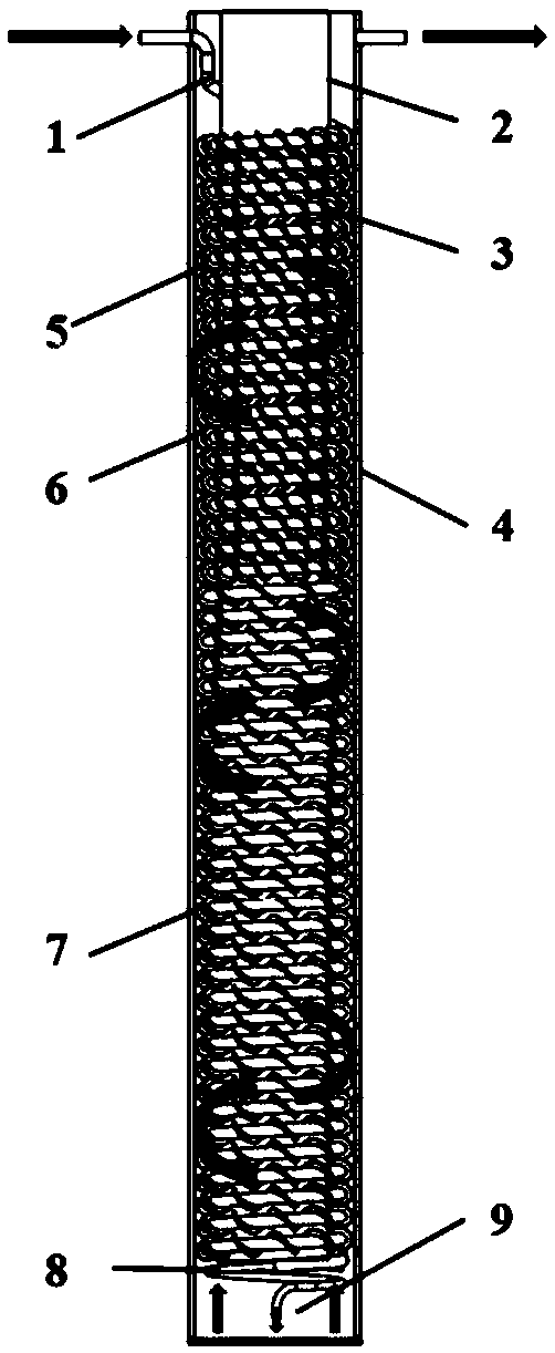
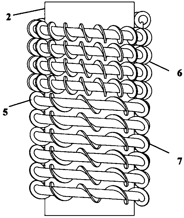
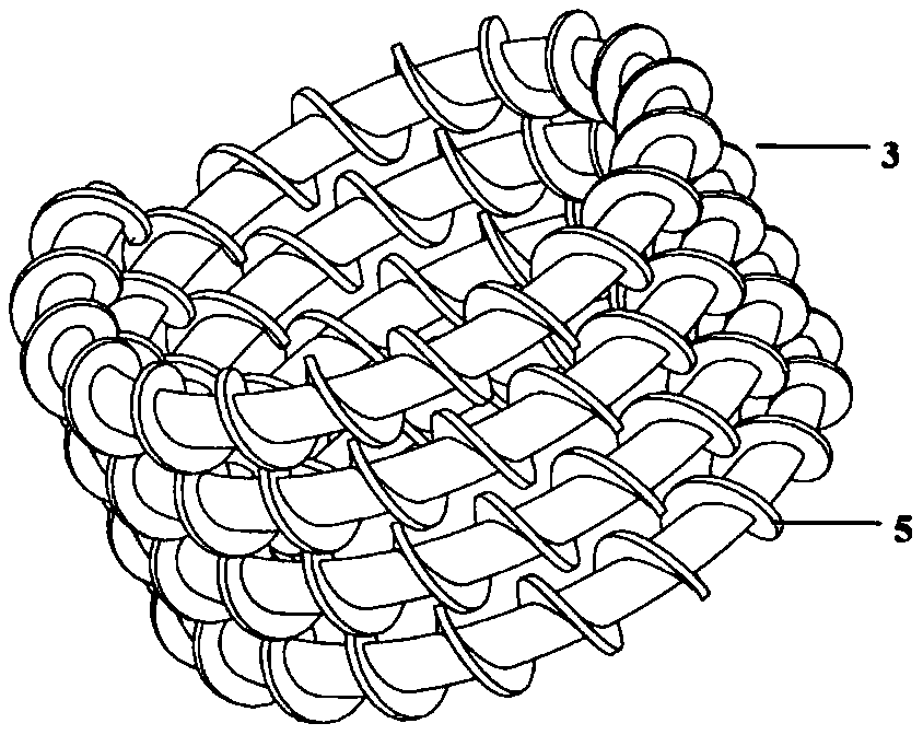
[0032] Such as figure 1 , Figure 2a , Figure 2bAs shown, this embodiment includes a mandrel 2 and a spiral capillary finned tube 3 spirally wound on the mandrel 2 in the axial direction. The shell 4 leaves a space to form an evaporation chamber 9. The spiral capillary finned tube 3 includes a capillary 1 and a spiral fin 5 wound on the capillary 1. The upper end of the sealed shell 4 is provided with a capillary inlet and a heat exchange tube respectively. The outlet of the capillary tube 1 is connected with the evaporation chamber 9, and a throttle valve 8 is also installed at the outlet; the spiral capillary finned tube 3 is divided into dense capillary finned tubes at the upper end according to the pitch of the spiral fins 5 6 and the sparse section of capillary finned tube 7 at the lower end form a structure of "dense top and sparse bottom", wherein the dense section of capillary finned tube 6 is located at the inlet of the thermal fluid, and the sparse section of capi...

Embodiment 2

[0039] The basic parameters are the same as those in Embodiment 1, but the pitch of each microelement of the helical capillary in the dense section and the sparse section changes linearly and continuously. The pitch calculation formula is shown in equation (6):

[0040]

[0041] In the formula: n=50, m=0.4n=20, α=0.3, β=1. By calculating the "upper denser lower sparser" structure in specific example 2 and comparing it with the two-stage "upper denser lower sparser" structure: Loss N d Basically the same, with a 24% reduction in material consumption.

Embodiment 3

[0043] This embodiment is a new type of countercurrent heat exchanger, specifically a countercurrent tube-row partition wall heat exchanger, which is composed of a base tube 10, dense fins 11, and sparse fins 12, such as Figure 4 shown. The dense fins 11 are located at the thermal fluid inlet section, the sparse fins 12 are located at the thermal fluid outlet section, and the boundary between the dense fins 11 and the sparse fins 12 is located at a position 40% to 50% away from the thermal fluid inlet. The hot fluid flows back and forth in the base pipe 10 , exchanges heat with the cold fluid through the fins, and at the same time cools itself. The structure of "dense top and sparse bottom" makes the heat exchange between the cold fluid and the hot fluid more intense at the dense fins 11, and the cooling effect on the hot fluid is better; while the resistance of the cold fluid at the sparse fins 12 is stronger small, flowing Losses are greatly reduced. The countercurrent ...


PUM


Abstract

The invention relates to an upper dense and lower sparse double spiral fin heat exchanger. The upper dense and lower sparse double spiral fin heat exchanger comprises a mandrel and a spiral capillaryfinned pipe spirally wound on the mandrel in the axial direction, a sealed housing sleeves the spiral capillary finned pipes, and a space for forming an evaporating chamber is located at the lower endof the mandrel and the housing. The spiral capillary finned pipe comprises a capillary pipe and spiral fins wound on the capillary pipe, a capillary pipe inlet and an outlet of the heat exchanger areformed in the upper end of the sealed housing correspondingly, and the capillary pipe outlet communicates with the evaporating chamber. The spiral capillary finned pipe is divided into an upper end dense section capillary finned pipe and a lower end sparse section capillary finned pipe according to the distance between the spiral fins. Hot fluid enters into the capillary finned pipe from an air inlet, after cooling by spiral flow from top to bottom in the pipe, and the heat load in the evaporating chamber is taken away and turned into cryogenic fluid; and then the cryogenic fluid is as cold fluid in a spirally flowing state on a circular channel formed by the mandrel, the capillary finned pipe and the housing from bottom to top, and the hot fluid in the capillary finned pipe is cooled andthe cryogenic fluid is discharged through an outlet pipe.

Description

technical field [0001] The invention relates to a heat exchanger used in the fields of infrared devices, low-temperature electronics, central air conditioners, etc., in particular to a double helical fin heat exchanger with dense top and sparse bottom. Background technique [0002] Utilizing the throttling refrigeration effect and the isentropic expansion refrigeration effect of gas to achieve refrigeration are the two most widely used methods in the field of refrigeration and cryogenic engineering, and throttling refrigeration has the advantages of simple structure and easy adjustment, and is often used in small cryogenic refrigerators. For example: Miniature J-T throttling refrigerators are widely used in infrared guidance systems because of their small size, light weight, fast cooling speed, no mechanical moving parts, and anti-electromagnetic interference. The regenerator in the miniature throttling refrigerator mainly adopts a double-helix counter-flow fin heat exchange...

Claims


Application Information

Patent Timeline
Patent Type & Authority Applications(China)
IPC IPC(8): F28D15/04F28F1/36
CPCF28D15/04F28F1/36
Inventor 陈慧刘迎文
Owner XI AN JIAOTONG UNIV
Why Eureka
Try Eureka