
Light-pen-type robot in-situ measurement system and method

An in-situ measurement and robot technology, applied in the field of precision measurement, can solve the problems of inability to measure the surface of the workpiece reasonably, reduce the machining accuracy of the workpiece, and affect the machining efficiency.

Active Publication Date: 2019-03-08
HUAZHONG UNIV OF SCI & TECH +1
View PDF6 Cites 14 Cited by
  • Summary
  • Abstract
  • Description
  • Claims
  • Application Information

AI Technical Summary

Problems solved by technology

The three-coordinate measuring machine has the characteristics of high measurement accuracy and wide range. However, because the three-coordinate measuring machine has a precise motion platform and grating unit, it needs to be placed in a clean room with constant temperature and humidity. The measurement of the workpiece must go through "processing-disassembly- Clamping-measurement-disassembly-clamping-reprocessing" several processes make it inevitable to introduce secondary clamping errors in the process of measurement and reprocessing, which not only reduces the processing accuracy of the workpiece, but also seriously affects the processing efficiency
This solution needs to accurately calibrate the positional relationship of the feature points on the light pen to realize the calculation of perspective transformation, and the manual hand-held measurement method is used to select points for measurement based on human experience, which cannot reasonably measure the features of the workpiece surface, especially for complex For the measurement of curved surface parts, a reasonable planning of the measurement path is one of the key steps to improve the measurement accuracy and efficiency

Method used


Image

  • Light-pen-type robot in-situ measurement system and method
  • Light-pen-type robot in-situ measurement system and method
  • Light-pen-type robot in-situ measurement system and method

Examples


Embodiment Construction

[0058] In order to make the object, technical solution and advantages of the present invention clearer, the present invention will be further described in detail below in conjunction with the accompanying drawings and embodiments. It should be understood that the specific embodiments described here are only used to explain the present invention, not to limit the present invention. In addition, the technical features involved in the various embodiments of the present invention described below can be combined with each other as long as they do not constitute a conflict with each other.

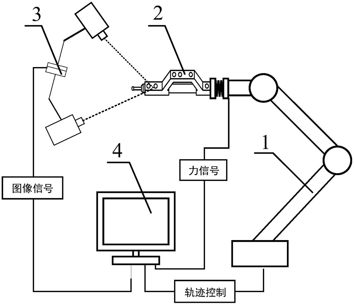
[0059] like figure 1 As shown, the light pen robot in-situ measurement system provided by the embodiment of the present invention includes an industrial robot 1, a light pen measurement unit 2, a binocular vision unit and an industrial computer 4, wherein:

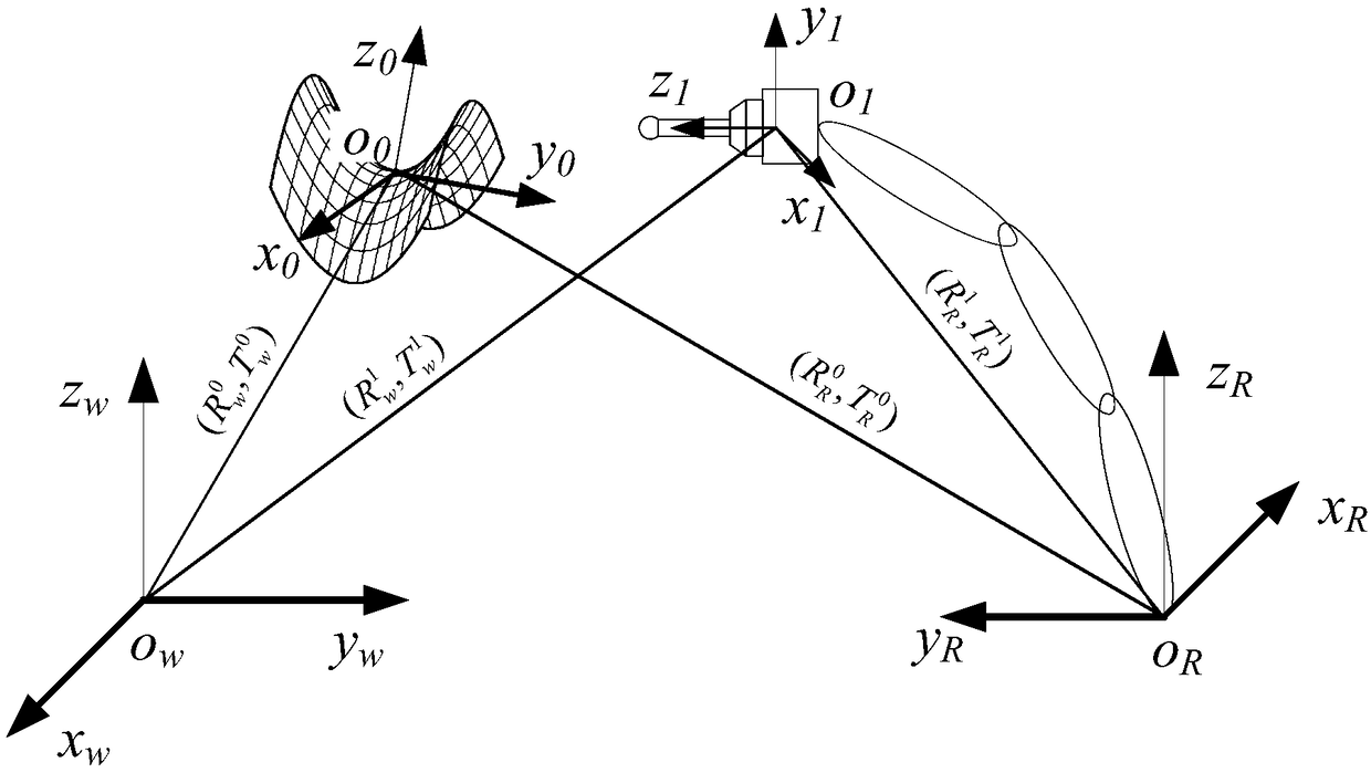
[0060] like figure 2 As shown, the light pen measurement unit 2 includes a flange 5, a force sensor 6, a retaining ring 7, a slider 8, a...


PUM


Abstract

The invention belongs to the precision measurement field and especially discloses a light-pen-type robot in-situ measurement system and method. The system mainly comprises an industrial robot, a lightpen measurement unit, a binocular visual unit and an industrial computer. A light pen, a probe, a spring, and a force sensor are arranged in the light pen measurement unit. The industrial robot clamps the light pen measurement unit to move according to a planned path so that the probe is flexibly contacted with a measured workpiece under the effect of the spring. At the same time, the binocular visual unit is used to collect light pen images in real time according to a set frame rate, and transmit to the industrial computer for image processing. A binocular visual three-dimensional reconstruction principle is used to calculate the position of a probe ball centre on a light pen, and based on this, probe ball head radius error compensation is performed at the combined force direction of a contact force collected by the force sensor, and then, the measurement result of a workpiece surface is acquired. The light pen measurement unit carries out automation measurement according to the planned path so that the efficiency and the precision of contour measurement are effectively increased.

Description

technical field [0001] The invention belongs to the field of precision measurement, and more specifically relates to an in-situ measurement system and method for a light pen robot. Background technique [0002] Product profile dimension measurement is a very important link in the product production process. At present, three coordinate measuring machines are often used in the industry for measurement. The three-coordinate measuring machine has the characteristics of high measurement accuracy and wide range. However, because the three-coordinate measuring machine has a precise motion platform and grating unit, it needs to be placed in a clean room with constant temperature and humidity. The measurement of the workpiece must go through "processing-disassembly- Clamping-measurement-disassembly-clamping-reprocessing" several processes make it inevitable to introduce secondary clamping errors in the process of measurement and reprocessing, which not only reduces the processing ac...

Claims


Application Information

Patent Timeline
IPC IPC(8): G01B11/00
Inventor 赵欢李昊杨拥萍陈茜谭峰丁汉
Owner HUAZHONG UNIV OF SCI & TECH
Learn More