
Water level monitoring device for reservoir

A technology for water level monitoring devices and reservoirs, applied in measuring devices, circuit devices, lubrication indicating devices, etc., can solve the problems of increased maintenance costs, large volume, short service life, etc. The effect of low difficulty

Inactive Publication Date: 2019-03-08
浙江景昌建设有限公司
View PDF8 Cites 2 Cited by
  • Summary
  • Abstract
  • Description
  • Claims
  • Application Information

AI Technical Summary

Problems solved by technology

[0002] As a water conservancy project for retaining flood water and regulating water flow, the reservoir plays a role in preventing flood disasters and brings a lot of convenience to people. However, when local heavy rains and floods occur and the water level exceeds the warning value, it may cause huge disasters and damage to downstream areas. loss
[0003] The monitoring device used in the reservoir in the prior art can assist in real-time monitoring of the water level of the reservoir and prevent flooding, but it has the following defects in the use process: 1. It is a single-column integrated structure, which is fixed by in-situ anchoring and has poor stability. The impact resistance is weak, it cannot withstand the impact of wind pressure and water waves for a long time, the service life is short, and it will eventually tilt or even fall over; 2. The overall length is long, the volume is large, it needs to be hoisted and transported, and the cost is high, and once the local structure is damaged , needs to be replaced as a whole, resulting in waste of resources and increased maintenance costs

Method used


Image

  • Water level monitoring device for reservoir
  • Water level monitoring device for reservoir
  • Water level monitoring device for reservoir

Examples


Embodiment Construction

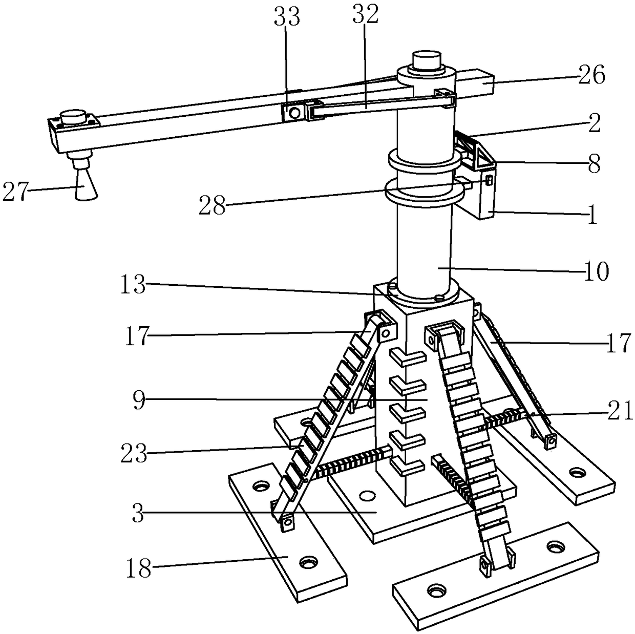
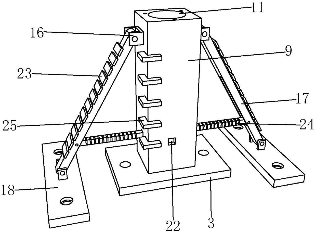
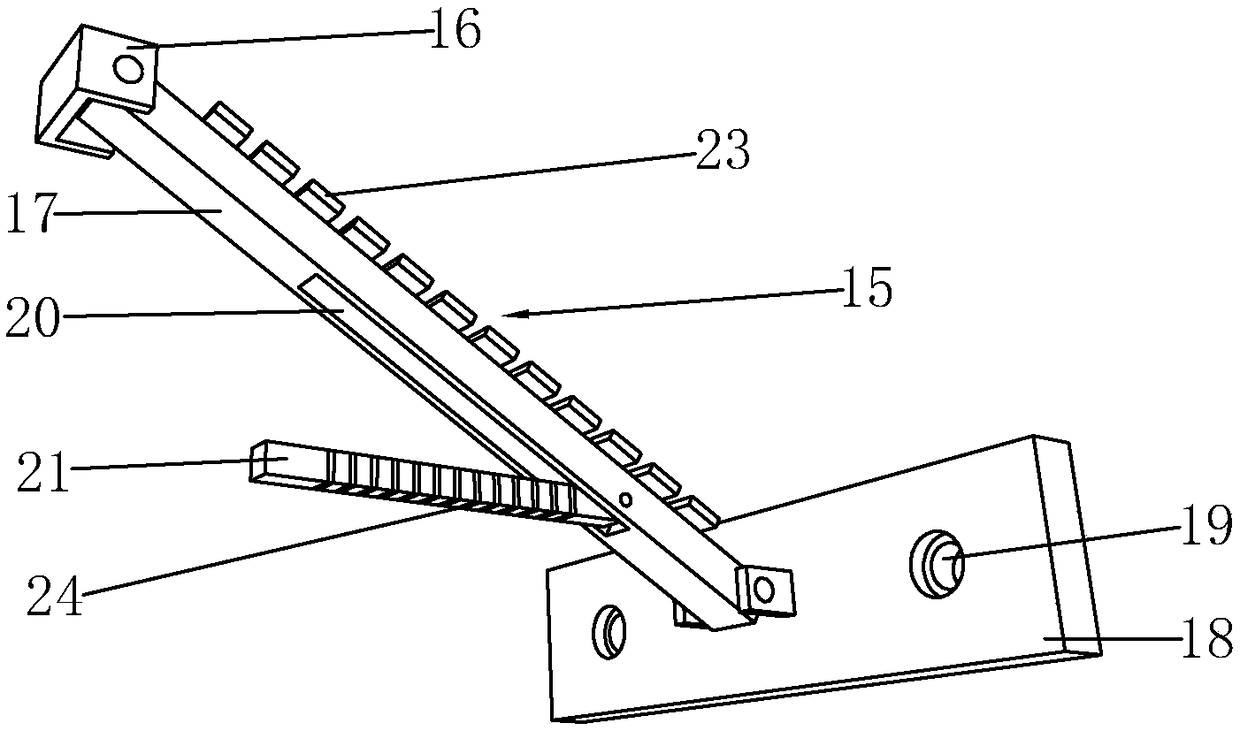
[0030] Such as Figure 1 to Figure 8 As shown, it is a reservoir water level monitoring device of the present invention, comprising a column, an equipment box 1 and a solar panel 2, the equipment box 1 and the solar panel 2 are respectively arranged on the column, and the bottom of the column is provided with an installation chassis 3, and the installation The bottom of the chassis 3 is provided with ground anchors 4, and the ground anchors 4 are driven into the ground below to realize the installation position positioning of the installation chassis 3, and cannot move freely, and then drive the anchors into the fixing holes 5 on the installation chassis 3 Bolts, to achieve local installation and fixation, stable and reliable. The equipment box 1 is provided with a controller 6 and a storage battery 7. The storage battery 7 is electrically connected to the controller 6 and the solar panel 2, respectively. The solar panel 2 converts light energy into electrical energy and trans...


PUM


Abstract

The invention discloses a water level monitoring device for a reservoir. The water level monitoring device comprises a stand column, an equipment box and a solar cell panel, the equipment box and thesolar cell panel are arranged on the stand column respectively, a mounting base plate is arranged at the bottom of the stand column, and a controller and a storage battery are arranged in the equipment box; the storage battery is connected with the controller and the solar cell panel, a supporting cross rod is arranged on the stand column, and a radar water level gauge is arranged on the supporting cross rod; the radar water level gauge is connected with the controller, supporting assemblies surround the stand columns, and each supporting assembly comprises a fixing base, a supporting rod anda supporting bottom plate; the supporting rods are movably connected between the fixing bases and the supporting bottom plates, the fixing bases are arranged on the stand column, anchoring holes are formed in the supporting bottom plates, containing grooves are formed in the supporting rods, positioning rods are movably connected in the containing grooves, positioning holes are formed in the standcolumn, and one end of each positioning rod is located in the corresponding positioning hole. The device is flexible in structural connection, stable, reliable, capable of adapting to various terrainconditions, high in impact resistance and long in service life.

Description

technical field [0001] The invention belongs to the technical field of water level monitoring, in particular to a water level monitoring device for a reservoir. Background technique [0002] As a water conservancy project for retaining flood water and regulating water flow, the reservoir plays a role in preventing flood disasters and brings a lot of convenience to people. However, when local heavy rains and floods occur and the water level exceeds the warning value, it may cause huge disasters and damage to downstream areas. loss. [0003] The monitoring device used in the reservoir in the prior art can assist in real-time monitoring of the water level of the reservoir and prevent flooding, but it has the following defects in the use process: 1. It is a single-column integrated structure, which is fixed by in-situ anchoring and has poor stability. The impact resistance is weak, it cannot withstand the impact of wind pressure and water waves for a long time, the service life...

Claims


Application Information

Patent Timeline
Patent Type & Authority Applications(China)
IPC IPC(8): G01F23/284G08C17/02H02J7/35
CPCG01F23/284G08C17/02H02J7/35
Inventor 严密刘学应蓝丽芳肖振西赵岳字陈伟罗浩
Owner 浙江景昌建设有限公司
Learn More