
Optical module extinction ratio adaptive adjustment device and control method thereof

A control method and extinction ratio technology, which is applied to lasers, laser components, semiconductor lasers, etc., can solve problems that affect the yield, time-consuming and labor-intensive production and debugging processes, and degraded optical eye diagrams, etc., to achieve the effect of mass production

Active Publication Date: 2020-08-18
THE 44TH INST OF CHINA ELECTRONICS TECH GROUP CORP
View PDF5 Cites 0 Cited by
  • Summary
  • Abstract
  • Description
  • Claims
  • Application Information

AI Technical Summary

Problems solved by technology

[0003] For the design and production of optical modules, the extinction ratio is one of the important indicators to measure the performance of the optical module. Without any compensation measures, the extinction ratio will change greatly in a wide temperature range, resulting in transmission errors. Bit rate surge
In actual design, if the extinction ratio is too small, the receiving sensitivity will be reduced, and if the extinction ratio is too large, the optical eye diagram will be degraded, and the receiving sensitivity will also be reduced; therefore, in a wide temperature range (-40℃~85℃) The extinction ratio must be kept within a certain narrow range to ensure the receiving sensitivity and thus ensure the correct transmission of data
In the past extinction ratio stabilization methods, most of them are based on open-loop control, which has the advantage of simple implementation and can stabilize the extinction ratio in a wide range, but the extinction ratio in this range has higher requirements for the consistency of the laser. , which is not conducive to the mass production of optical modules, affects the yield rate, and the production and debugging process is time-consuming and laborious

Method used


Image

  • Optical module extinction ratio adaptive adjustment device and control method thereof
  • Optical module extinction ratio adaptive adjustment device and control method thereof
  • Optical module extinction ratio adaptive adjustment device and control method thereof

Examples


Embodiment Construction

[0044] In order to make the purpose, technical solutions and advantages of the present invention clearer, the technical solutions in the embodiments of the present invention will be clearly and completely described below in conjunction with the accompanying drawings. Obviously, the described embodiments are only part of the embodiments of the present invention, and Not all examples.

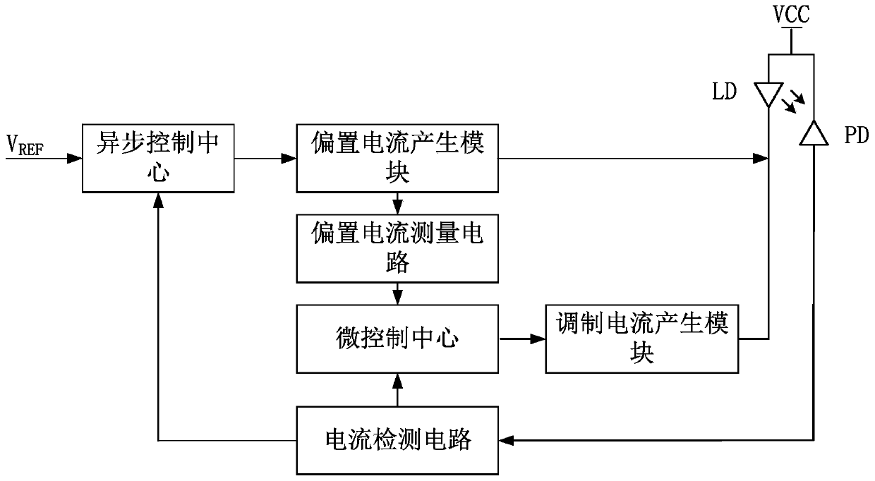
[0045] Such as figure 1 As shown, an optical module extinction ratio adaptive adjustment device of the present invention includes: a detector, a laser, an asynchronous control center, a bias current generation module, a bias current measurement circuit, a current detection circuit, a micro control center, a modulation current generation module and voltage reference V REF ;

[0046] Among them, the detector is connected with the current detection circuit, and the current detection circuit is respectively connected with the asynchronous control center and the micro control center, and the voltage...


PUM


Abstract

The invention relates to a laser control technology, in particular to an optical module extinction ratio self-adaptive device and a control method thereof. The optical module extinction ratio self-adaptive adjustment device comprises a detector, a laser, an asynchronous control center, a bias current generating module, a bias current measuring circuit, a current detecting circuit, a micro-controlcenter, a modulation current generating module and a voltage reference VREF. After adoption of the scheme, the device can automatically correct a bias current and a modulation current acting on the laser according to the current change of the laser, so that an optical module, under the condition of a wide temperature range, keeps stable optical power and extinction ratio output.

Description

technical field [0001] The invention relates to a laser control technology, in particular to an optical module extinction ratio adaptive adjustment device and a control method thereof. Background technique [0002] In modern information networks, optical fiber communication technology has gradually replaced the traditional cable transmission technology and occupies a dominant position. As the coverage of the information network becomes wider and wider, the optical module is the core device of the optical fiber communication network, and its demand is increasing and the scope of use is becoming wider and wider. [0003] For the design and production of optical modules, the extinction ratio is one of the important indicators to measure the performance of the optical module. Without any compensation measures, the extinction ratio will change greatly in a wide temperature range, resulting in transmission errors. Bit rate surged. In actual design, if the extinction ratio is too...

Claims


Application Information

Patent Timeline
Patent Type & Authority Patents(China)
IPC IPC(8): H01S3/13H01S5/068
CPCH01S3/1305H01S5/06808
Inventor 胡伟周本军胡俊豪李欢韦宜伶
Owner THE 44TH INST OF CHINA ELECTRONICS TECH GROUP CORP
Learn More