

Carbon nanotube surface plating method
A carbon nanotube and plating technology, which is applied in the direction of nanotechnology, nanotechnology, solid-state chemical plating, etc., can solve the problems of high processing cost, easily damaged carbon nanotube structure, and difficult quality control, and achieves a simple and easy preparation method The effect of the operation
- Summary
- Abstract
- Description
- Claims
- Application Information
AI Technical Summary
Problems solved by technology
Method used
Image

Examples
Embodiment 1
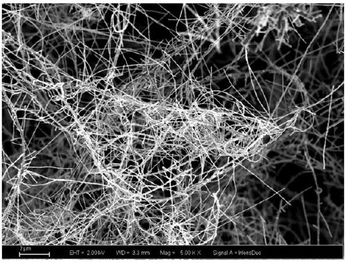
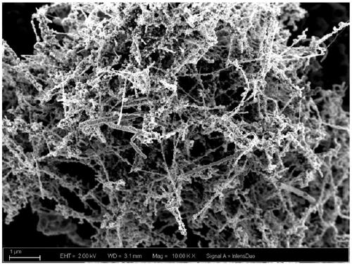
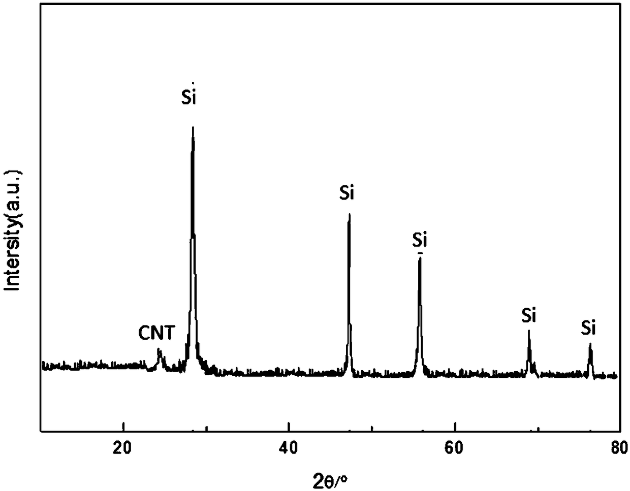
[0023] In this embodiment, the coating of a silicon layer on the surface of carbon nanotubes is taken as an example for illustration, and the specific steps are as follows:
[0024] S 1 , respectively weighing whisker-shaped multi-walled carbon nanotubes and silicon iodide according to the molar ratio of carbon to silicon of 1:0.5-2.0, mixing evenly and compacting;
[0025] S 2 , connect the compacted carbon nanotubes and silicon iodide mixture with a pair of graphite electrodes, then evacuate and argon in turn, repeat the operation 3 times until the air is completely removed, and then evacuate, so that the compacted carbon nanotubes The tube and the silicon iodide mixture are under vacuum, and the vacuum degree is maintained at 9.0×10 -8 mbar;
[0026] S 3 , pass in a pulse current, the current size is 10mA-100A, preferably 1A, the current pulse time is 0.1-10s, heat the mixture of carbon nanotubes and silicon iodide to 1100 ° C, silicon iodide is pyrolyzed, and silicon i...
Embodiment 2
[0031] This embodiment is illustrated by coating a titanium layer on the surface of carbon nanotubes as an example, and the specific steps are as follows:
[0032] S 1 , according to the carbon-titanium molar ratio of 1:0.6-1.8, respectively weigh whisker-shaped multi-walled carbon nanotubes and titanium iodide, mix uniformly and compact;
[0033] S 2 , connect the compacted carbon nanotubes and titanium iodide mixture with a pair of graphite electrodes; then evacuate and pass argon gas in sequence, repeat the operation 3 times until the air is completely removed, and then evacuate, so that the compacted carbon nanotubes The tube and the titanium iodide mixture are under vacuum, and the vacuum degree is maintained at 9.0×10 -8 mbar;
[0034] S 3 , pass a pulse current, the current size is 10mA-100A, preferably 0.5A, the current pulse time is 0.1-5s, heat the mixture of carbon nanotubes and titanium iodide to 700 ° C, titanium iodide pyrolyzes, and forms on the surface of c...
PUM
| Property | Measurement | Unit |
|---|---|---|
| Grain size | aaaaa | aaaaa |
| Grain size | aaaaa | aaaaa |
Abstract
Description
Claims
Application Information