In situ and real time quality control in additive manufactu process

An additive manufacturing and process technology, applied in the field of in-situ and real-time quality control in the additive manufacturing process

Active Publication Date: 2019-03-15
联邦材料测试与开发研究所
View PDF8 Cites 7 Cited by
  • Summary
  • Abstract
  • Description
  • Claims
  • Application Information

AI Technical Summary

Problems solved by technology

According to CN102680263, the use of optical sensors can improve the quality of additive manufacturing methods due to real-time detection of optical parameters, but there are still many unsolved problems to be solved, which cannot be solved by a simple combination of prior art documents

Method used


Image

  • In situ and real time quality control in additive manufactu process
  • In situ and real time quality control in additive manufactu process
  • In situ and real time quality control in additive manufactu process

Examples


Embodiment Construction

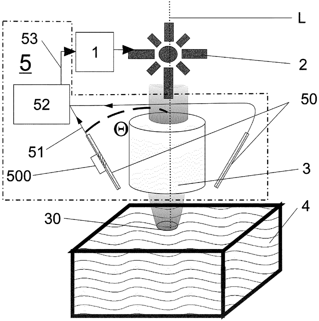
[0033] The purpose of the present invention is to introduce a novel method for quality control of additive manufacturing (AM) processes, in particular based on ion beam, microwave or laser powder sintering or melting (for powder bed and ion and electron beam, microwave or laser powder deposition). The method is intended to be an independent feedback control loop, providing real-time online monitoring of the additive manufacturing process. Furthermore, an apparatus using the method is disclosed.

[0034] Additive manufacturing device including ion and electron beam, microwave or laser irradiation system, ion and electron beam, microwave or laser irradiation system including ion and electron beam, microwave or laser electronic device 1 controlled ion and electron beam, microwave or laser source 2 , ion and electron beam, microwave or laser focusing device 3, ion and electron beam, microwave or laser focusing device 3 irradiates ion and electron beam, microwave or laser source 2...


PUM

PropertyMeasurementUnit
diameteraaaaaaaaaa

Abstract

The disclosed invention discloses the use of a sensor read out system with at least one fiber optical sensor (50), which is connected via at least one signal line (51) to a processing unit (52) as part of an additive manufacturing setup, for in situ and real time quality control of a running additive manufacturing process, wherein acoustic emission is measured via the at least one fiber optical sensor (50) in form of fibers with Bragg grating, fibre interferometer or Fabry-Perot structure (500), followed by a signal transfer (51) and an analysis of the measured signals in the processing unit (52), estimation of the sintering or melting process quality due to correlation between sintering or melting quality and measured acoustic emission signals and subsequent adaption of ion and electron beams, microwave or laser sintering or melting parameters of a ion and electron beams, microwave or laser electronics (1) of the additive manufacturing setup in real times via a feedback loop (53) as aresult of the measured acoustic emission signals after interpretation with an algorithmic framework in the processing unit (52).

Description

technical field [0001] The invention describes the use of a sensor readout system (5) with at least one fiber optic sensor (50) connected to a processing unit (52) via at least one signal line (51) , the sensor readout system (5) is used as a part of the additive manufacturing device for in-situ and real-time quality control of the ongoing ion and electron beam, microwave or laser additive manufacturing process; an ion and electron beam, microwave or laser In-situ and real-time quality control methods for additive manufacturing processes in laser sintering or melting devices, with controllable ion and electron beam, microwave or laser parameters during the ongoing additive manufacturing process, using a combination of ion and electron beams, Ion and electron beams, microwave or laser sources (2) controlled by microwave or laser electronics (1) and ion and electron beam, microwave or laser focusing devices (3) combine ion and electron beams, microwave or laser beams into ions a...

Claims


Application Information

Patent Timeline
Patent Type & Authority Applications(China)
IPC IPC(8): G01D5/353B22F3/105B33Y30/00G01N29/12
CPCG01N29/12B22F2999/00G01D5/35354B33Y30/00G01N29/14G01N29/22G01N29/2418B29C64/153B29C64/393Y02P10/25G01D5/35316B22F10/28B22F10/36B22F10/25B22F12/44B22F12/90B22F2202/01B22F10/00B22F10/10B22F10/20B22F10/30
Inventor K·瓦斯默S·舍夫奇克F·瓦基利法拉哈尼G·维奥拉基斯S·沃谢
Owner 联邦材料测试与开发研究所
Why Eureka
Try Eureka