Vibronic sensor

An electronic vibration and sensor technology, applied in the direction of instruments, flow characteristics, scientific instruments, etc., can solve the problems that can no longer ensure accurate measurement of density, and achieve the effect of simple measurement principle and speed increase

Active Publication Date: 2019-03-15
EHNDRESS KHAUZER GMBKH KO KG
View PDF14 Cites 0 Cited by
  • Summary
  • Abstract
  • Description
  • Claims
  • Application Information

AI Technical Summary

Problems solved by technology

[0013] The fundamental limitation arises from the empirical assumption that the measurement of a definite, predeterminable phase shift is vi...

Method used


Image

  • Vibronic sensor
  • Vibronic sensor
  • Vibronic sensor

Examples


Embodiment Construction

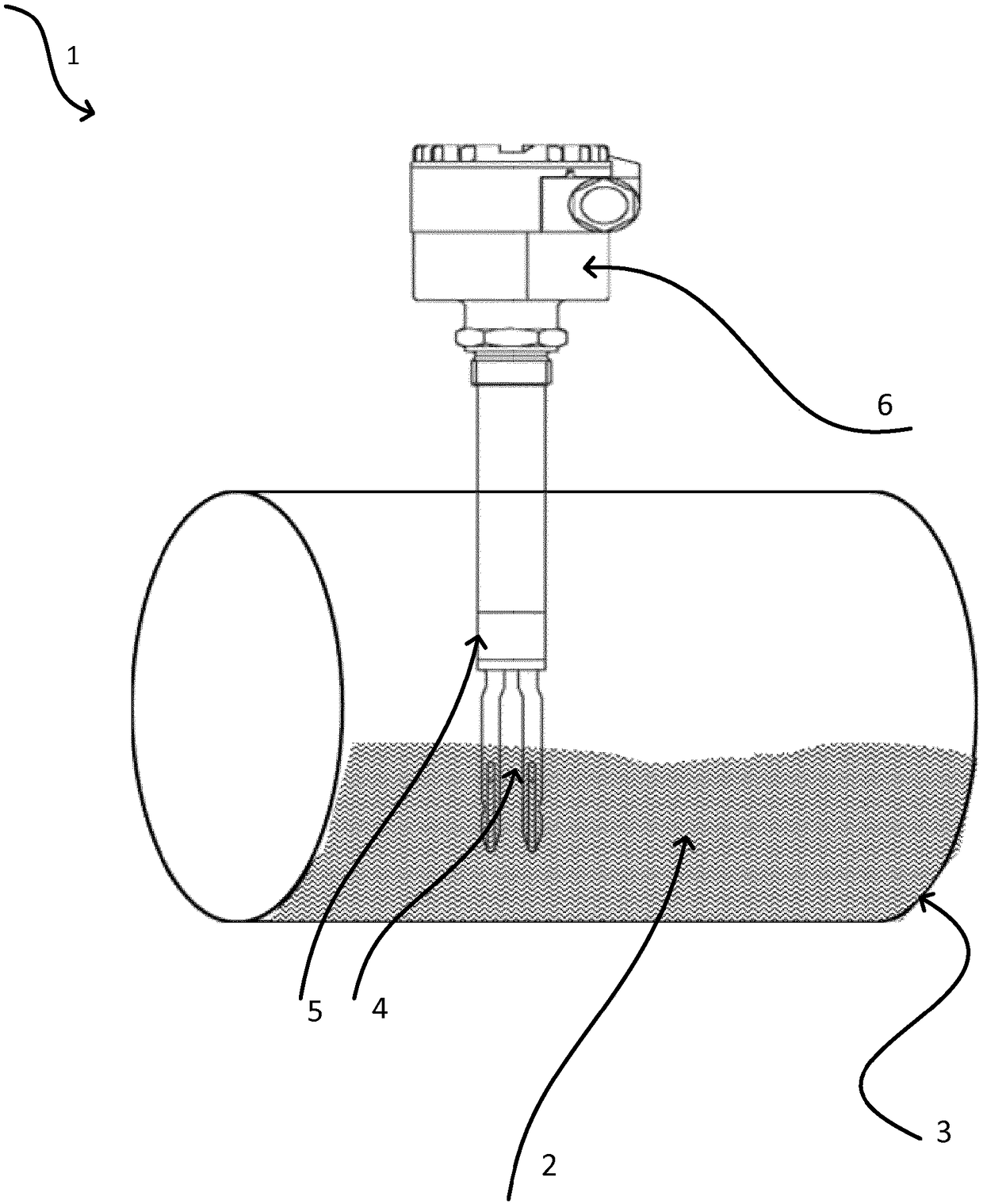
[0051] figure 1 An electronic vibration sensor 1 is shown comprising an oscillatable unit 4 in the form of an oscillating fork which extends partially into a medium 2 located in a container 3 . The oscillatable unit is excited by an exciter / receiver unit 5, eg a piezoelectric stack or a bimorph driver, to perform mechanical oscillations. However, it should be understood that other embodiments of the electronic vibration sensor are also within the scope of the present invention. An electronic unit 6 is also provided, via which signal recording, evaluation and / or feedback takes place.

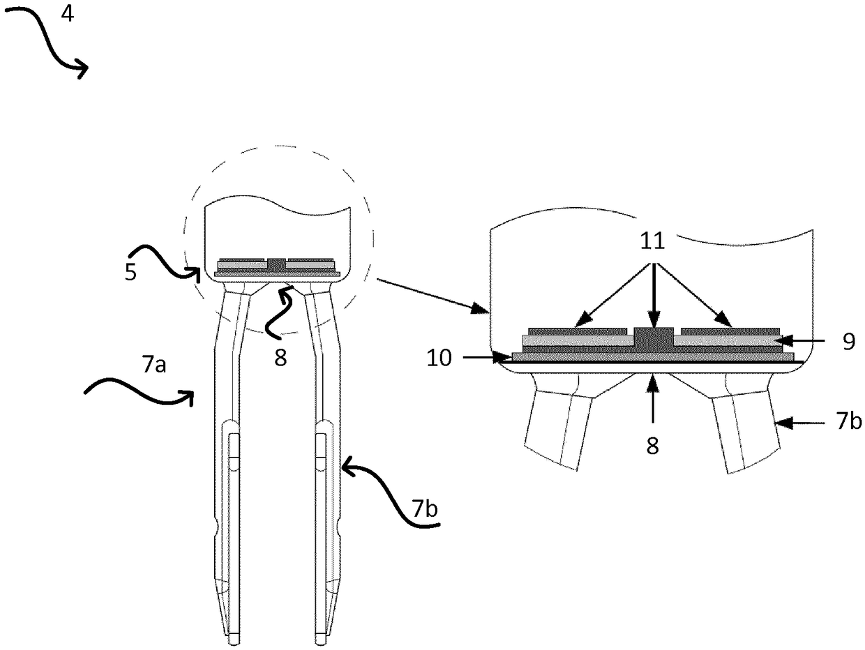
[0052] figure 2 An oscillatable unit 4 in the form of an oscillating fork is shown, such as integrated into, for example, an electronic vibration sensor sold by the applicant under the trademark LIQUIPHANT. The oscillating fork 4 comprises two oscillating tines 7 a and 7 b connected to a membrane 8 . In order for the oscillating teeth 7 a , 7 b to perform a mechanical oscillation, a force is...


PUM


Abstract

The invention relates to a method for determining and/or monitoring the density (p) and/or the viscosity (v) of a medium (3) in a container (2) by means of a vibronic sensor (1), and a corresponding sensor (1). A vibrateable unit (4) is caused to mechanically vibrate by means of an electrical excitation signal (UA), and the mechanical vibrations of the mechanically vibrateable unit (4) are received and converted into an electrical receive signal (UE). In addition, the excitation signal (UA) is generated from the receive signal (UE) in such a way that at least one predeterminable phase shift (delta(phi)) occurs between the excitation signal (UA) and the receive signal (UE), wherein a frequency (f) of the excitations signal (UA) is determined from the receive signal (UE) with the occurrenceof the predeterminable phase shift (delta(phi)). Furthermore, a damping (D) and/or a damping (D)-dependent variable is/are determined from the receive signal (UE) with the occurrence of the predeterminable phase shift (delta(phi)), and the density (p) and/or the viscosity (v) of the medium is/are determined at least from the damping (D) and/or the damping (D)-dependent variable, and from the frequency (f) of the excitation signal (UA).

Description

technical field [0001] The invention relates to a method for determining and / or monitoring the density and / or viscosity of a medium in a container by means of an electronic vibration sensor and to a device suitable for carrying out the method. Background technique [0002] Electronic vibration sensors are used extensively in process and / or automation technology. In a fill level measuring device, the device comprises at least one mechanically oscillatable unit, eg an oscillating fork, a single tooth or a membrane. It is excited during operation by a drive / receiver unit, usually in the form of an electromechanical transducer unit, to perform mechanical oscillations. The drive / receive unit can be, for example, a piezoelectric drive or an electromagnetic drive. In a flow measuring device, however, the mechanically oscillatable unit can also be embodied as an oscillatable tube, for example in a measuring device operating according to the Coriolis principle, through which the me...

Claims


Application Information

Patent Timeline
IPC IPC(8): G01F23/296G01N11/16
CPCG01F23/2967G01N9/002G01N11/16G01N2009/006
Inventor 托比亚斯·布伦加藤纳曼纽尔·绍特迈斯特萨沙·德安杰利科
Owner EHNDRESS KHAUZER GMBKH KO KG
Why Eureka
Try Eureka