Medicine material flow equalizing device for propellant extruder

A technology for extruders and propellants, applied in explosives, explosives processing equipment, offensive equipment, etc., can solve the problems of slow flow rate of charge, waste of charge, affecting the uniformity of charge density, etc., to achieve the flow rate of charge Balance and improve the effect of current sharing effect

Active Publication Date: 2019-03-19
SICHUAN UNIV
View PDF9 Cites 1 Cited by
  • Summary
  • Abstract
  • Description
  • Claims
  • Application Information

AI Technical Summary

Problems solved by technology

[0003] However, when extruded by the existing propellant extruder, the flow rate of the material located at the core of the extrusion cavity is slow, and the flow rate of the material located at the periphery of the extrusion cavity is fast, so that the material located at the core of the extrusion cavity within the same time period The outflow is smaller than the outflow of the drug material located at the periphery of the extrusion chamber, which is not conducive to the subsequent drug cutting process, resulting in waste of drug material, and also affects the uniformity of the extruded drug column density

Method used


Image

  • Medicine material flow equalizing device for propellant extruder
  • Medicine material flow equalizing device for propellant extruder
  • Medicine material flow equalizing device for propellant extruder

Examples


Embodiment 1

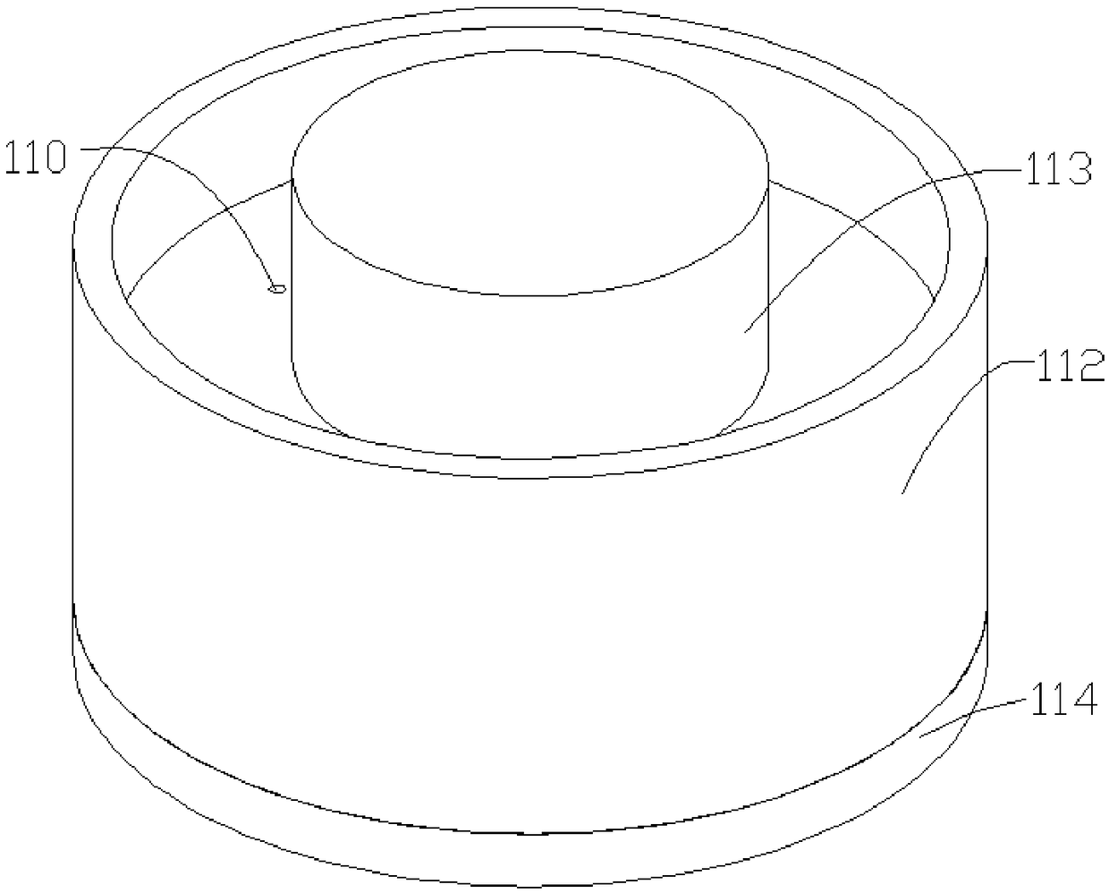
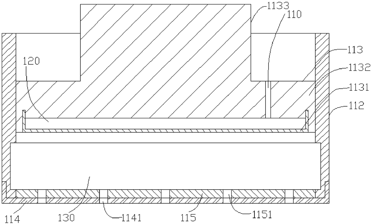
[0025] In this embodiment, the drug material flow equalization device used for propellant extruder is as figure 1 , figure 2 As shown, it includes an outer cylinder 112 , a mold body 114 , a piston 113 and a rubber gasket 115 .

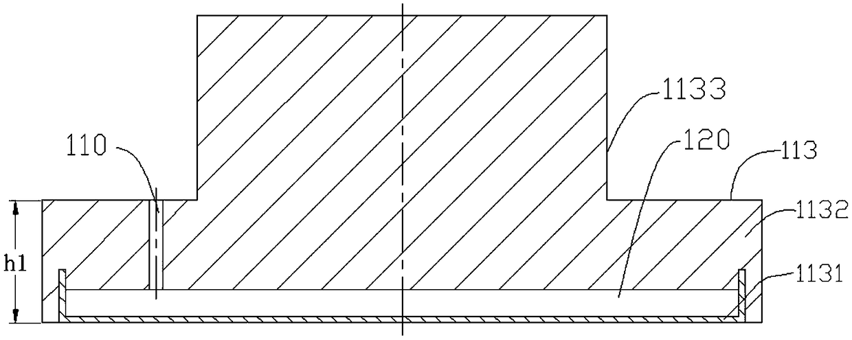
[0026] The piston 113 is as figure 2 , image 3 As shown, it is composed of a piston body 1132, a piston rod 1133 and a rubber disc 1131. The piston rod 1133 is installed on the top surface of the piston body 1132. When installing, the center line of the piston rod and the center line of the piston body should be on a straight line, and the piston body The bottom of 1132 is provided with a groove, and the top surface is provided with a vent hole 110 communicating with the groove. The size of the rubber disk 1131 matches the groove, and the rubber disk is fixed on the bottom of the piston body by vulcanization and covers the groove , and the bottom surface of the rubber disc 1131 is flush with the bottom surface of the piston body 1132 , so that t...

Embodiment 2

[0032] In this embodiment, the drug material flow equalization device used for propellant extruder is as figure 1 , figure 2 As shown, it includes an outer cylinder 112 , a mold body 114 , a piston 113 and a rubber gasket 115 . The structure difference from Example 1 is: aperture D2=aperture D1+L.


PUM


Abstract

The invention discloses a medicine material flow equalizing device for a propellant extruder. The device comprises an outer cylinder, a mold body, a piston and a rubber pad, wherein the piston consists of a piston body, a piston rod and a rubber disc; a groove is formed in the bottom of the piston body; a ventilation hole communicated with the groove is formed in the top surface of the piston body; the rubber disc is fixed at the bottom of the piston body to enable a groove cavity of the groove to become an air storage chamber; inner holes of the outer cylinder are sequentially a pore diameterD1 section, a pore diameter D2 section and a pore diameter D3 section from top to bottom, and D2 > D1, D3 = D1; a plurality of medicine outlet holes with the same shape and size are formed in the mold body, through holes with the same position, number, size and shape as the medicine outlet holes on the mold body are formed in the rubber pad, and each through hole on the rubber pad is respectivelyaligned with the corresponding medicine outlet hole on the mold body when the rubber pad is fixedly connected with the mold body; and the piston body is mounted in the pore diameter D1 section, the rubber pad is mounted in the pore diameter D3 section, the mold body covers the bottom of the outer cylinder and is fixedly connected with the wall of the outer cylinder, and the pore diameter D2 section and the top surface of the rubber pad form a medicine material extrusion cavity.

Description

technical field [0001] The invention belongs to the technical field of propellant extrusion molding, and relates to a charge equalizing device for a propellant extruder. Background technique [0002] The propellant is the gunpowder used to complete the projectile task. In order to release its energy regularly, the propellant must have a specific shape. The main molding and processing method of propellant is extrusion method, that is, the plasticized propellant powder is extruded from the mold with a certain pressure. During the extrusion process, the propellant powder undergoes viscous flow and viscoelastic deformation, thus A powder column with a certain shape and size is obtained. [0003] However, when extruded by the existing propellant extruder, the flow rate of the material located at the core of the extrusion cavity is slow, and the flow rate of the material located at the periphery of the extrusion cavity is fast, so that the material located at the core of the extr...

Claims


Application Information

Patent Timeline
Patent Type & Authority Applications(China)
IPC IPC(8): C06B21/00
CPCC06B21/0075
Inventor 李文强李孟葵惠茜赵武李传晓王凯
Owner SICHUAN UNIV
Why Eureka
Try Eureka