
Low-damping capacitive acceleration sensor and preparation method thereof

An acceleration sensor, capacitive technology, applied in the measurement of acceleration, speed/acceleration/shock measurement, instruments, etc., can solve the problems of unreachable, high sensitivity, unadjustable, etc., to reduce the damping coefficient of the film, reduce the system noise, The effect of increasing sensitivity

Active Publication Date: 2019-03-19
浙江宏振智能芯片有限公司
View PDF7 Cites 11 Cited by
  • Summary
  • Abstract
  • Description
  • Claims
  • Application Information

AI Technical Summary

Problems solved by technology

Facts have proved that due to the defects of its own structure and existing technology, the existing capacitive acceleration sensors generally have the following problems: one, the existing capacitive acceleration sensors only use a single capacitance such as variable pitch or variable area The structure of the sensor cannot achieve high sensitivity; secondly, the capacitive plates of the existing capacitive acceleration sensors are flat, which cannot effectively reduce the air damping; thirdly, due to the limitations of the existing dry etching process Limitation, the existing capacitive acceleration sensor wants to get a larger initial capacitance, the capacitor plate is prone to tilt, so it is difficult to obtain a larger initial capacitance; Fourth: the initial capacitance of the existing capacitive acceleration sensor is fixed value, it cannot be adjusted after the process is completed

Method used


Image

  • Low-damping capacitive acceleration sensor and preparation method thereof
  • Low-damping capacitive acceleration sensor and preparation method thereof
  • Low-damping capacitive acceleration sensor and preparation method thereof

Examples


Embodiment 1

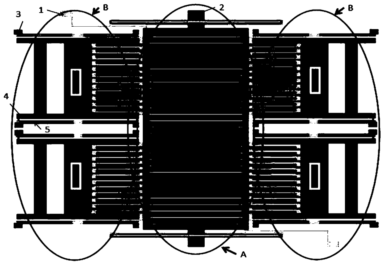
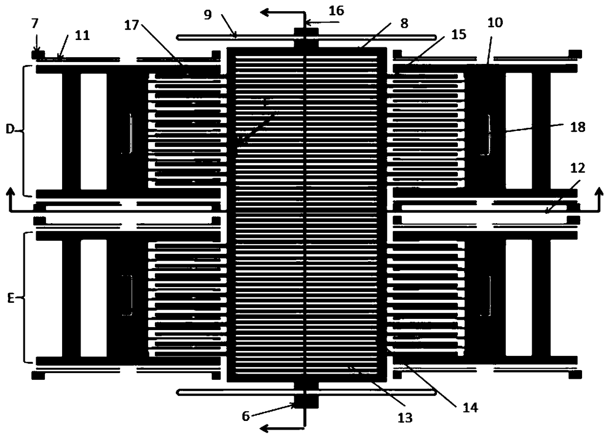
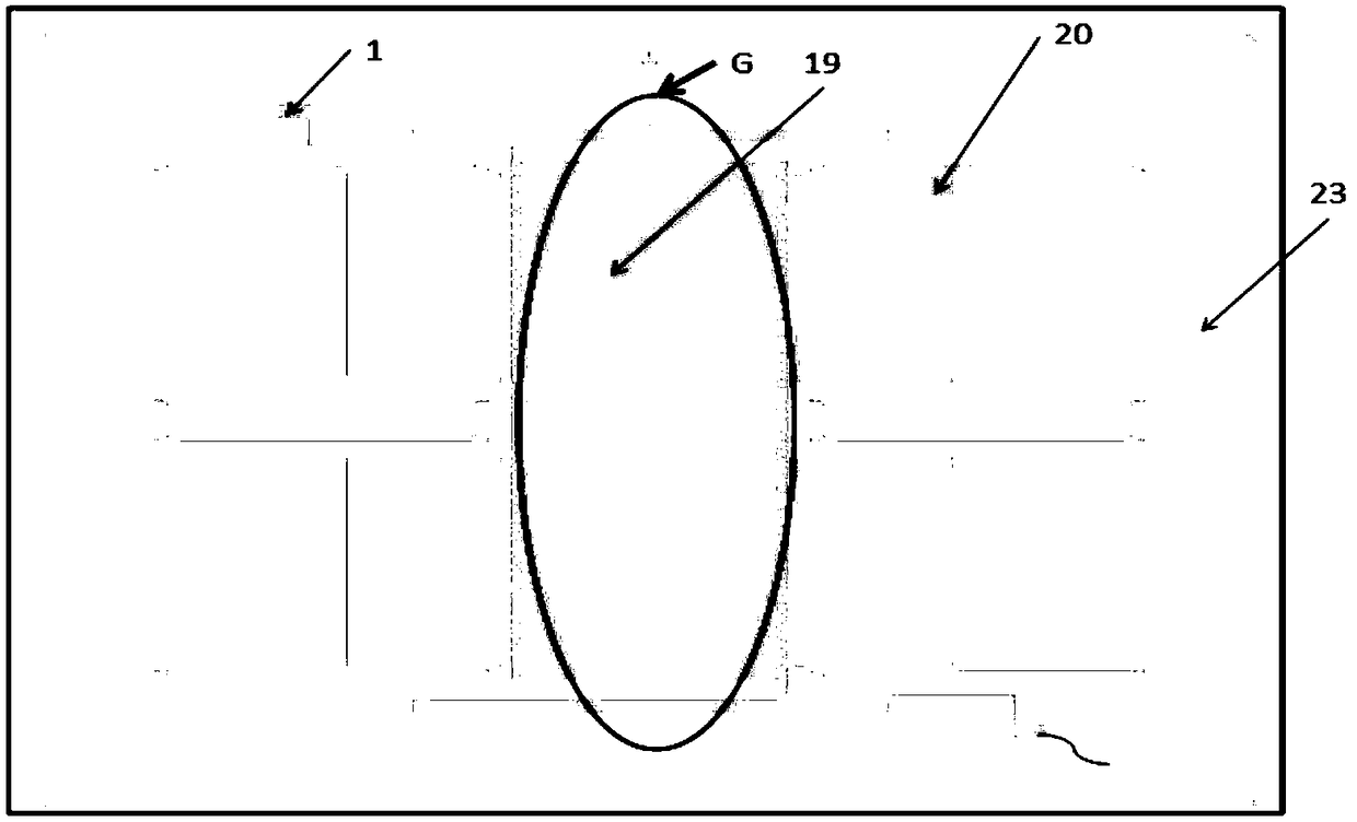
[0044] combine Figure 1 to Figure 5 , the overall structure of the present invention will be described.

[0045] A low-damping capacitive acceleration sensor comprises a glass substrate 23 and an aluminum electrode 19 on its upper surface, a first electrode lead point 1 on the aluminum electrode 19, a first anchor point 6 and a second anchor point fixed on the glass substrate 23. An anchor point 7, a second electrode lead point 2 on the first anchor point 6, a third electrode lead point 3 on the second anchor point 7, a silicon sensitive mass 8 that can move longitudinally over the aluminum electrode 19, The first U-shaped silicon cantilever beam 9 that connects the first anchor point 6 with the silicon sensitive mass 8, the silicon fixed electrode 10 that is suspended above the aluminum electrode 19 and can move longitudinally, connects the second anchor point 7 with the silicon fixed electrode 10 connected to the second U-shaped silicon cantilever beam 11 , the second alum...


PUM

PropertyMeasurementUnit
Thicknessaaaaaaaaaa
Thicknessaaaaaaaaaa

Abstract

The invention provides a low-damping capacitive acceleration sensor and a preparation method thereof. The low-damping capacitive acceleration sensor consists of a variable separation distance type capacitive structure and a variable area type capacitive structure. The variable separation distance type capacitive structure adopts a comb tooth shaped electrode plate structure, the separation distance between a capacitive movable electrode plate and a fixed electrode plate is decreased in an electrostatic driving mode, the preparation problem of a comb tooth shaped electrode structure with high depth-width ratio of a dry-method etching process is solved, and initial capacitance of the prepared acceleration sensor is effectively improved. An inverted triangular groove structure is also etchedin the fixed electrode plate of a variable separation distance type capacitor. Compared with a reported rectangular groove structure, the air damping is greatly reduced, and the sensor has better fidelity. By combining the variable separation distance type capacitive structure and the variable area type capacitive structure, the sensitivity of the sensor can be effectively improved, and the air damping can be reduced. The sensor is large in initial capacitance, small in damping, low in noise and high in sensitivity, a preparation process is simple, and the cost can be reduced.

Description

technical field [0001] The invention relates to a capacitive acceleration sensor, in particular to a low-damping capacitive acceleration sensor and a preparation method thereof. Background technique [0002] Capacitive acceleration sensors have the advantages of small size, high measurement accuracy, high sensitivity, low power consumption, good stability, and small temperature coefficient. Automotive electronics, consumer products, navigation and other fields. Facts have proved that due to the defects of its own structure and existing technology, the existing capacitive acceleration sensors generally have the following problems: one, the existing capacitive acceleration sensors only use a single capacitance such as variable pitch or variable area The structure of the sensor cannot achieve high sensitivity; secondly, the capacitive plates of the existing capacitive acceleration sensors are flat, which cannot effectively reduce the air damping; thirdly, due to the limitation...

Claims


Application Information

Patent Timeline
IPC IPC(8): G01P15/125B81C1/00
CPCB81C1/00166G01P15/125
Inventor 刘超然王益哨董林玺王高峰
Owner 浙江宏振智能芯片有限公司
Learn More