Fluorescence imaging system and fluorescence imaging method for quantitative detection of spatial distribution of photosensitizer

A fluorescent imaging and spatial distribution technology, applied in the field of biomedical imaging, can solve problems such as difficult calibration, complex structure, and inability to reflect the concentration distribution of photosensitizers, and achieve the effect of precise positioning

Inactive Publication Date: 2019-03-22
FUJIAN NORMAL UNIV
View PDF8 Cites 3 Cited by
  • Summary
  • Abstract
  • Description
  • Claims
  • Application Information

AI Technical Summary

Problems solved by technology

At present, fluorescence spectroscopy technology is usually used in clinical practice for fluorescence detection and combined with calibration algorithms to realize quantitative monitoring of photosensitizer concentration. The measurement method often produces contact pressure, changes the local optical characteristic parameters of the tissue, and affects the accuracy of the measurement; in addition, the spectral detection method can only obtain the information of a single point, and cannot reflect the concentration distribution of the photosensitizer in the target tissue with a large area
Fluorescence imaging technology can detect the concentration distribution of photosensitizers in a large target tissue by imaging. However, in the imaging mode, the light detected by each pixel on the imaging surface comes from the sampling signal in a certain volume of the tissue. The average value of ; the imaging surface may also receive photons from outside the target tissue, making the correction of fluorescence signals based on imaging techniques more difficult than that based on spectral techniques
Existing fluorescence imaging systems often use a semi-empirical ratio algorithm, that is, perform a ratio operation between the fluorescence image and the reflected light data. Such a fluorescence imaging system is not only complex in structure, expensive, but also unable to analyze the absorption and scattering characteristic parameters of the tissue separately. Can be applied to specific tissue samples
At the same time, when the excitation light with a uniform distribution of illumination intensity reaches a specific tissue depth, it can only excite the photosensitizer at this depth, and cannot correctly reflect the concentration distribution information of the photosensitizer at different depths around it.

Method used


Image

  • Fluorescence imaging system and fluorescence imaging method for quantitative detection of spatial distribution of photosensitizer
  • Fluorescence imaging system and fluorescence imaging method for quantitative detection of spatial distribution of photosensitizer
  • Fluorescence imaging system and fluorescence imaging method for quantitative detection of spatial distribution of photosensitizer

Examples


Embodiment Construction

[0035] The present invention will be further described below in conjunction with the drawings and embodiments.

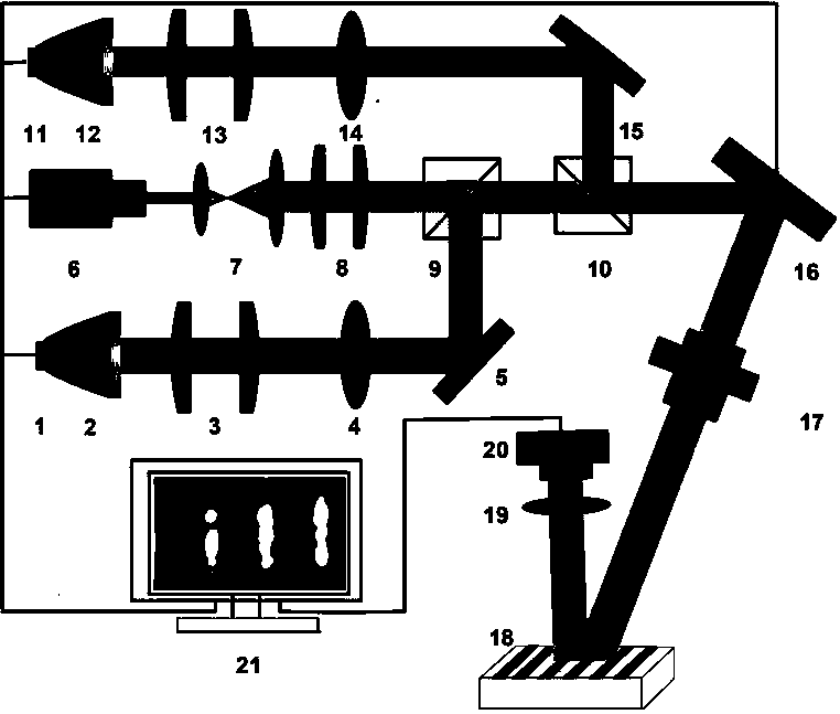
[0036] Please refer to figure 1 , The present invention provides a fluorescent imaging system for quantitatively detecting the spatial distribution of photosensitizers, which includes a first LED light source 1, a first free-form surface total reflection lens 2, a first fly-eye lens 3, a first integrator lens 4, and a first mirror 5. , The second LED light source 11, the second free-form surface total reflection lens 12, the second fly-eye lens 13, the second integrator lens 14, the second mirror 15, the first half mirror 9, the second half mirror 10. Laser light source 6, beam expander 7, third fly-eye lens 8, digital micromirror 16, projection lens 17, condenser lens 19, CMOS camera 20, and computer 21. The light emitted by the first LED light source 1 passes through the total reflection of the first free-form surface total reflection lens 2 to form a collimated lig...


PUM


Abstract

The invention relates to a fluorescence imaging system for quantitative detection of spatial distribution of a photosensitizer. The fluorescence imaging system is characterized by comprising a first LED light source, a first freeform-surface total reflection lens, a first fly-eye lens, a first integrated lens, a first reflection mirror, a second LED light source, a second freeform-surface total reflection lens, a second fly-eye lens, a second integrated lens, a second reflection mirror, a first semi-transparent semi-reflective mirror, a second semi-transparent semi-reflective mirror, a laser light source, a beam expander, a third fly-eye lens, a digital micromirror device, a projection lens, a condensing lens, a CMOS (complementary metal oxide semiconductor) camera and a computer. The fluorescence imaging system has the advantages that diffuse reflection images are adopted to quantitatively calibrate the effect of tissue optical properties on fluorescence images, quantitative fluorescence imaging of the spatial distribution of the photosensitizer is realized, and the spatial distribution and variation conditions of the concentration of the photosensitizer in diseased tissue are obtained.

Description

Technical field [0001] The invention relates to the field of biomedical imaging, and relates to a fluorescence imaging system and method for quantitatively detecting the spatial distribution of a photosensitizer. Background technique [0002] The use of photosensitizers can form a relatively high concentration of accumulation in tumor tissues and can produce fluorescence after being irradiated with light of appropriate wavelengths. Fluorescence detection technology can be applied clinically. By analyzing the fluorescence intensity, not only the growth position of the diseased tissue and the lesion can be determined The boundary between tissue and normal tissue, as well as the treatment area, can also monitor the changes in photosensitizer concentration in real time during photodynamic therapy, and guide real-time dose adjustment, so as to realize fluorescence diagnosis, surgical guidance and treatment monitoring of tumors and other diseases. A wide range of clinical applications....

Claims


Application Information

Patent Timeline
Patent Type & Authority Applications(China)
IPC IPC(8): A61B5/00
CPCA61B5/0071
Inventor 刘丽娜李春林胡梦雪林黎升李步洪
Owner FUJIAN NORMAL UNIV
Why Eureka
Try Eureka