Microfluidic chip as well as preparation method and detection method thereof

A microfluidic chip and chip technology, which is applied in the direction of chemical instruments and methods, measuring devices, instruments, etc., can solve the problems of inability to carry out multi-item detection at the same time, low chip manufacturing output, complex chip packaging process, etc., and achieve strict response time Controllability, improved detection repeatability, simple packaging effect

Pending Publication Date: 2019-03-22
迪亚莱博(张家港)生物科技有限公司
View PDF5 Cites 14 Cited by
  • Summary
  • Abstract
  • Description
  • Claims
  • Application Information

AI Technical Summary

Problems solved by technology

However, the active microfluidic chip POCT integrated with magnetic particle detection technology, because the magnetic particles coated with different antibodies cannot be separated by a magnetic field, the main defect of this detection technology is that it can only perform single-item detection. The control chip cannot perform multi-item detection at the same time
The active microfluidic chip POCT with integrated pressure valve needs to integrate an elastic film in the chip, which makes the entire chip packaging process extremely complicated, resulting in low chip manufacturing yield

Method used


Image

  • Microfluidic chip as well as preparation method and detection method thereof
  • Microfluidic chip as well as preparation method and detection method thereof
  • Microfluidic chip as well as preparation method and detection method thereof

Examples


Embodiment 1

[0048] Embodiment 1 microfluidic chip

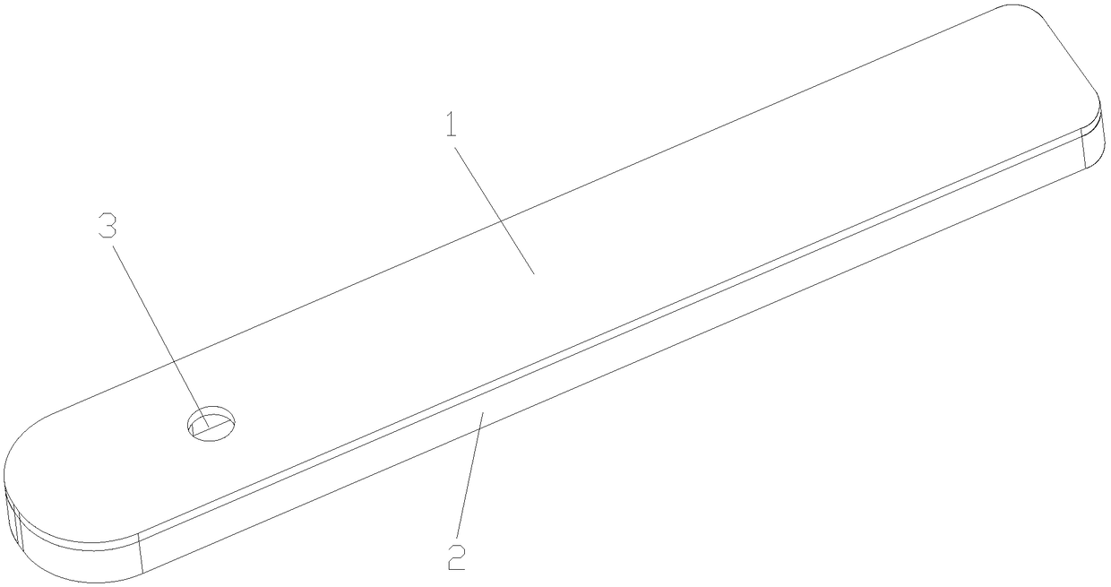
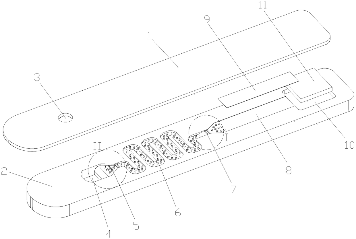
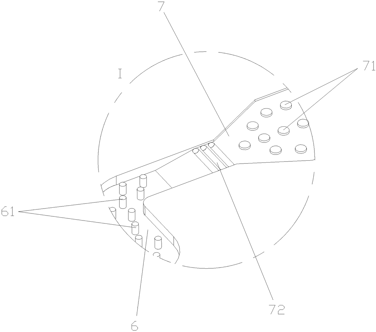
[0049] Such as Figure 1-4 As shown, a microfluidic chip in this embodiment includes a chip substrate 2 and a chip cover plate 1. The chip cover plate 1 is provided with a sample port 3 for adding a test sample, and the chip substrate 2 is sequentially opened with a sample port 3 for adding a sample. The reaction chamber 4 below the sample port 3, the mixing pipe 6 connected with the reaction chamber 4, the detection pipe 8 connected with the mixing pipe 6, and the waste liquid tank 10. Paper 11. In this embodiment, the detection pipeline 8 has a depth of 200 μm, and the waste liquid tank 10 has a depth of 1 mm; in other embodiments, the detection pipeline 8 has a depth ranging from 50 μm to 1000 μm, and the waste liquid tank 10 has a depth ranging from 0.2 mm to 2 mm.

[0050] The mixing pipeline 6 is coated with a fluorescent microsphere labeling reagent for providing a fluorescent detection signal, and the detection pipeline 8 is lo...

Embodiment 2

[0059] Embodiment 2 The preparation method of microfluidic chip

[0060] This embodiment provides a preparation method based on the microfluidic chip described in Embodiment 1, which specifically includes the following steps:

[0061] Step 1) Preparation of fluorescent microsphere labeling reagent

[0062] The purified detection antibody raw material is labeled by the time-resolved fluorescent microsphere analysis method, and the fluorescent microsphere marker is collected as the fluorescent microsphere labeling reagent.

[0063] Step 2) Preparation of Capture Antibody Reagent

[0064] The purified capture antibody raw material is diluted with a diluent, and the diluted capture antibody raw material is labeled on nano polystyrene microspheres to prepare a capture antibody reagent.

[0065] The diluent in this example is 10 mM PBS.

[0066] Step 3) Superhydrophilic modification of the chip surface material

[0067]The method of vacuum plasma bombardment or atmospheric plasm...

Embodiment 3

[0081] Example 3 Detection method of microfluidic chip

[0082] This embodiment provides a detection method based on the microfluidic chip described in Embodiment 1, which specifically includes the following steps:

[0083] Step A. Add sample and mix well

[0084] Add the sample with the pipette gun, draw the test sample and add it to the sample hole of the above-mentioned bonded microfluidic chip, then place the microfluidic chip that has been loaded into the card slot of the detection instrument, and the loading of the microfluidic chip The sample hole is combined with the gas circuit driving device of the instrument, and the gas circuit driving device is controlled to generate alternating positive and negative pressures in the sample injection hole, driving the detection sample to flow back and forth in the reaction chamber and mixing pipe in the chip, redissolving and mixing The fluorescent microsphere labeling reagent in the pipeline is uniformly mixed with it at the sam...


PUM

PropertyMeasurementUnit
depthaaaaaaaaaa
heightaaaaaaaaaa
widthaaaaaaaaaa

Abstract

The invention discloses a microfluidic chip as well as a preparation method and a detection method thereof. The microfluidic chip comprises a chip substrate and a chip cover plate, wherein the chip cover plate is provided with a sample adding opening for adding a detection sample; the chip substrate is provided with a reaction cavity located below the sample adding opening, a uniform mixing pipeline communicated with the reaction cavity, a detection pipeline communicated with the uniform mixing pipeline, and a waste liquid groove in sequence; a fluorescent microsphere labeling reagent for providing a fluorescent detection signal is arranged in the uniform mixing pipeline in a coating mode; a carrier film is loaded in the detection pipeline; the carrier film is coated with at least one capturing antibody reagent. The microfluidic chip disclosed by the invention can realize strict control of the re-dissolving volume and reaction time of a reagent and the detection repeatability is improved; the microfluidic chip is simple to package, the production technology of the chip is extremely simplified and the yield of the chip is improved; different regions in the carrier film can be coatedwith not less than one type of capturing antibody and multi-item combined detection is realized.

Description

technical field [0001] The invention belongs to the technical field of in vitro diagnosis of medical devices, and in particular relates to a microfluidic chip used for bedside diagnosis (POCT) and a preparation method and a detection method of the microfluidic chip. Background technique [0002] Point of Care Testing (POCT) refers to the on-site rapid diagnosis of patients with the help of miniaturized or moderate desktop equipment or reagents. Because the POCT detection method has the characteristics of simple and convenient operation, easy maintenance of the detection system, detection anytime and anywhere, and low detection cost, POCT detection products are gradually accepted and promoted by the market. [0003] POCT detection products used for disease diagnosis in the prior art can be roughly divided into two categories according to detection methodology or product materials: chromatography POCT detection technology and microfluidic POCT detection technology. [0004] C...

Claims


Application Information

Patent Timeline
Patent Type & Authority Applications(China)
IPC IPC(8): B01L3/00G01N33/533G01N33/577
CPCG01N33/533G01N33/577B01L3/5027B01L2200/10
Inventor 顾悦蒋理国
Owner 迪亚莱博(张家港)生物科技有限公司
Why Eureka
Try Eureka