

Power circuit and photovoltaic power generation system including power circuit
A photovoltaic power generation system and power circuit technology, applied in photovoltaic power generation, circuit devices, AC network circuits, etc., can solve the problems of large electromagnetic radiation, shortened life, electromagnetic environmental pollution, etc., and achieve simple circuit implementation, high reliability, and low cost cheap effect
- Summary
- Abstract
- Description
- Claims
- Application Information
AI Technical Summary
Problems solved by technology
Method used
Image

Examples
no. 1 example
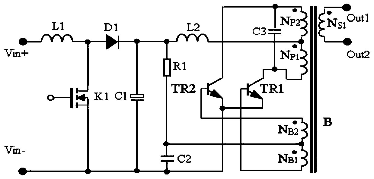
[0060] see figure 1 , figure 1 It is a schematic diagram of the power circuit of the first embodiment of the present invention. The composition and connection relationship of its components are as follows:
[0061] figure 1 The power supply circuit shown includes a BOOST circuit and a CCFL conversion circuit;
[0062] BOOST circuit includes MOS tube K1, diode D1, inductor L1 and capacitor C1;
[0063] The CCFL oscillating circuit includes a starting circuit composed of resistor R1 and capacitor C2, capacitor C3, inductor L2, transistor TR1, transistor TR2, transformer B, primary windings NP1 and NP2, feedback windings NB1 and NB2, and secondary winding NS1. The circuit includes at least two terminals, one end of the resistor R1 is the start-up input end, and the connection point between the other end of the resistor R2 and one end of the capacitor C2 is the start-up output end. This embodiment is a device that provides start-up current for two oscillating transistors TR...
no. 2 example
[0097] Figure 4 It is the improved schematic diagram of the power supply circuit applied to the photovoltaic power generation system according to the second embodiment of the present invention. Since there is equivalently a diode in series with the photovoltaic string, in order to improve the activation effect, a set of DC The power supply E, that is, a set of DC power supply E connected in series with the photovoltaic string, the series connection method is one of the following two ways:
[0098] (1) The negative pole of the DC power supply is electrically connected to the second output end of the power supply circuit, the first output end of the power supply circuit is electrically connected to the positive pole of the photovoltaic string, and the negative pole of the photovoltaic string is electrically connected to the positive pole of the DC power supply;
[0099] (2) The negative pole of the DC power supply is electrically connected to the positive pole of the photovolta...
no. 3 example
[0103] Figure 5 It is the schematic diagram of the power supply circuit of the third embodiment of the present invention. The difference between the third embodiment and the first embodiment is that the resistor R1 is replaced by a constant current source, and the current direction is consistent, so that when the input voltage of the CCFL conversion circuit drops, Due to the existence of the constant current source, the current provided to the bases of the two push-pull transistors TR1 and TR2 is constant, so that the input voltage of the power supply circuit can be wider. As mentioned above, when the operating voltage drops from 319V to 36V , since the base current provided by the constant current source to the triode TR1 or TR2 does not decrease, the CCFL converter will not stop oscillating. In order to adapt to the wide range of terminal voltages of photovoltaic strings. The working principle of this embodiment and its application in the photovoltaic power generation syste...
PUM
| Property | Measurement | Unit |
|---|---|---|
| Resistance | aaaaa | aaaaa |
Abstract
Description
Claims
Application Information