Film coating machine flattening roller layout structure and film coating machine using the same

A layout structure and flattening roller technology, which is applied in the field of coating machine flattening roller layout structure, can solve problems such as inconsistency and difficulty in adjusting the direction of the flattening rollers, achieve thick coating thickness, meet coating thickness requirements, and be easy to adjust Effect

Pending Publication Date: 2019-03-29
四川海格锐特科技有限公司
View PDF0 Cites 2 Cited by
  • Summary
  • Abstract
  • Description
  • Claims
  • Application Information

AI Technical Summary

Problems solved by technology

[0007] The purpose of the present invention is to provide a layout structure of the flattening rollers of a coating machine, which solves the problem that due to the need for back-and-forth coating, the coating process must be completed at the position of the main roller, and the angles of the flattening rollers in the two directions are different. When one direction is adjusted so that there is no wrinkle and the coating process is completed, it is more difficult to adjust the direction of the flattening roller when the strip runs in the opposite direction

Method used


Image

  • Film coating machine flattening roller layout structure and film coating machine using the same

Examples


Embodiment 1

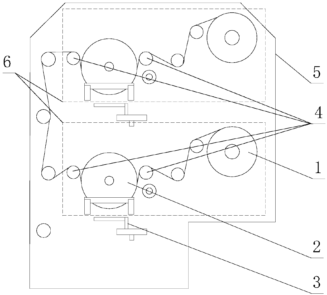
[0044] A coating machine flattening roller layout structure, including a main roller 2; also includes at least two flattening rollers 4, the flattening rollers 4 are respectively located on both sides of the input surface and the output surface of the main roller 2; 2. The flattening rollers 4 on both sides are different from the active surfaces of the main roller 2 and the strip.

Embodiment 2

[0046] The difference between this embodiment and Embodiment 1 is that the flattening rollers 4 located on both sides of the main roller 2 are symmetrical about the straight axis where one diameter of the main roller 2 is located.

Embodiment 3

[0048] The difference between this embodiment and Embodiment 1 is that the axes of the flattening rollers 4 located on both sides of the main roller 2 are located on the same horizontal plane.


PUM


Abstract

The invention discloses a film coating machine flattening roller layout structure. The structure includes a vacuum chamber and film coating components arranged in the vacuum chamber. The film coatingcomponents include a strip transfer system and evaporation sources. The strip transfer system includes two reeling wheels, two main rollers and the two evaporation sources. When the equipment works, one of the two reeling wheels is used as a winding wheel and the other is used as an unwinding wheel. In a strip transfer path, the two main rollers are located between the two reeling wheels, one of the two main rollers acts on one side of a strip, and the other main roller acts on the other side of the strip. The two evaporation sources are both used for vaporizing a material to be coated, and one of the evaporation sources and one of the main rollers form a film coating station. At any film coating station, gas phase obtained by heating through the evaporation sources acts on a strip sectionthat is bonded to the main rollers. The equipment can realize double-sided film coating of materials and help to obtain thicker film coating thickness.

Description

technical field [0001] The invention relates to the field of coating equipment, in particular to a layout structure of flattening rollers of a coating machine. Background technique [0002] Vacuum coating refers to a method of heating metal or non-metallic materials under high vacuum conditions to evaporate and condense on the surface of the coating (metal, semiconductor or insulator) to form a thin film. For example, vacuum aluminum plating, vacuum copper plating, etc. [0003] Vacuum coating technology is generally divided into two categories, namely physical vapor deposition (PVD) technology and chemical vapor deposition (CVD) technology. [0004] Physical vapor deposition technology refers to the method of vaporizing the plating material into atoms, molecules or ionizing it into ions under vacuum conditions, using various physical methods, and directly depositing it on the surface of the substrate. The preparation of hard reaction films is mostly made by physical vapor...

Claims


Application Information

Patent Timeline
Patent Type & Authority Applications(China)
IPC IPC(8): C23C14/24C23C14/56
CPCC23C14/24C23C14/243C23C14/562
Inventor 陈清胜赵锐
Owner 四川海格锐特科技有限公司
Why Eureka
Try Eureka