Liquid-spraying spinning device

A spinning device and liquid jet technology, applied in the field of spinning, can solve the problems of inconsistent spinning performance, inhomogeneous properties, and influence of volatilization, and achieve the effects of avoiding physical harm, avoiding different spinning thicknesses, and being easy to observe

Active Publication Date: 2019-03-29
上海固甲新材料科技有限公司 +1
View PDF14 Cites 2 Cited by
  • Summary
  • Abstract
  • Description
  • Claims
  • Application Information

AI Technical Summary

Problems solved by technology

[0005] However, the existing solution jet spinning device has some disadvantages, which directly affect the safety, effectiveness and wide use of the equipment. The specific disadvantages are as follows:
[0006] (1) Application of polymer materials: the existing solution jet spinning solution is a static solution before being extruded from the nozzle, that is, after the solute (polymer) is dissolved in the solvent, it undergoes a certain mixing method (such as heating or stirring) Form a solution, inject it into the spinning die, and then spray it out from the nozzle in a static manner. This method is only suitable for spinning conventional polymer materials. For some polymer materials with high viscosity and poor fluidity, static solution When the method is extruded, the extrusion pressure is relatively high, and it is difficult to form spun fibers with a smaller diameter;
[0007] (2) Safety issues: the existing spinning environment is an open environment, and the solvent of the spinning solution is usually an organic sol

Method used


Image

  • Liquid-spraying spinning device
  • Liquid-spraying spinning device
  • Liquid-spraying spinning device

Examples


Embodiment 1

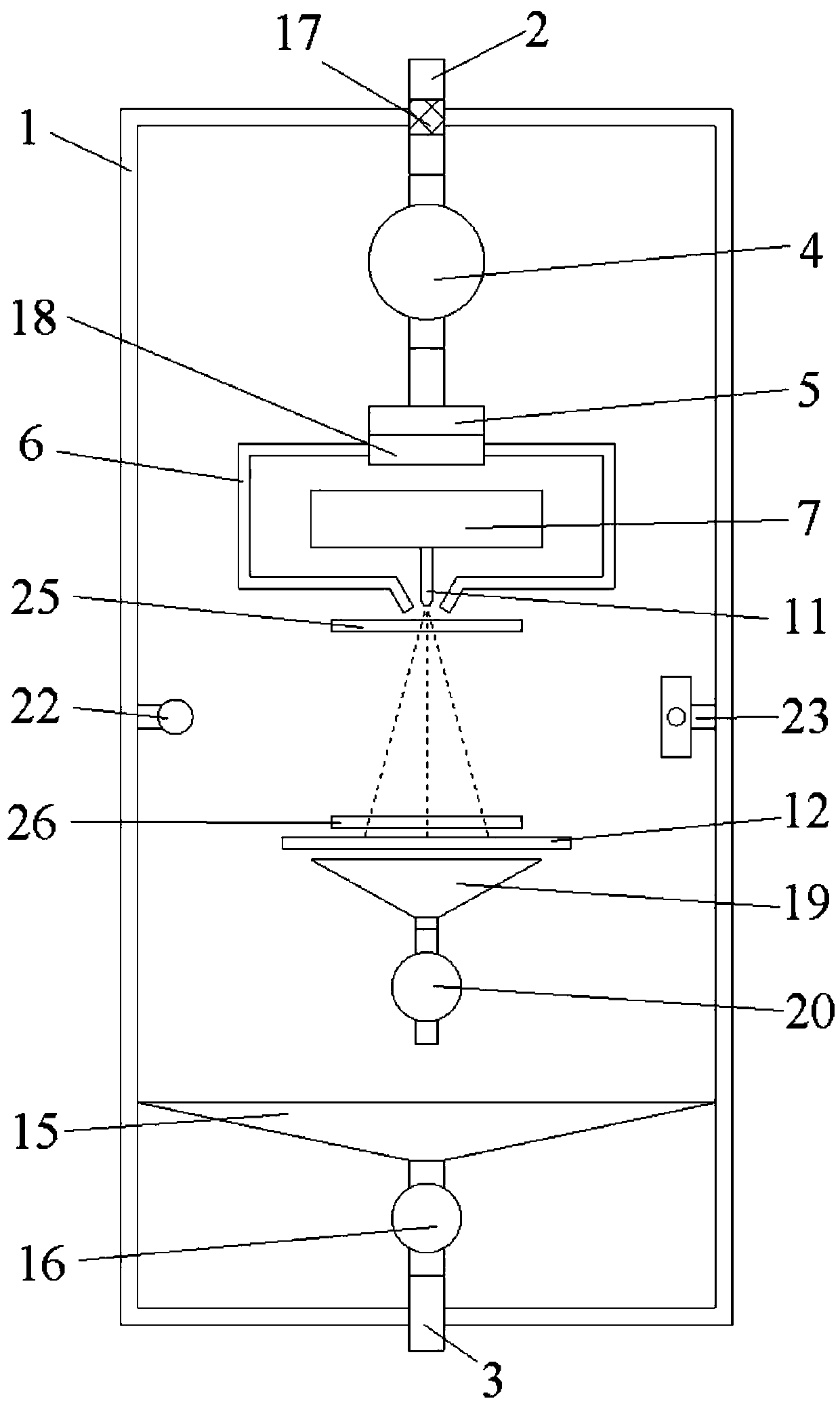
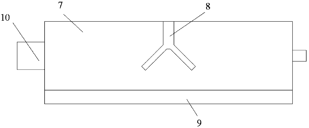
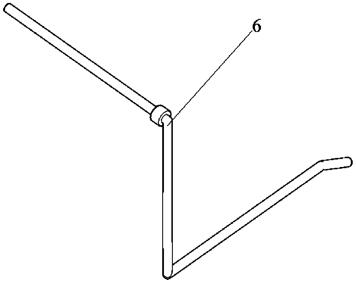
[0055] This embodiment is an exemplary embodiment of the present invention, such as Figure 1~4 As shown, among them, figure 1 It is a top view of the airtight box of this embodiment, a liquid jet spinning device, comprising an airtight box 1, the airtight box 1 includes an air inlet 2 and an air outlet 3, and the air inlet 2 is arranged at the bottom of the airtight box 1 The first end and the air outlet 3 are arranged at the second end of the airtight box 1 .

[0056] Further, a filtering device 17 is provided in the air inlet 2 , and the filtering device 17 is used to filter the gas entering through the air inlet 2 to prevent the gas from carrying impurities into the airtight box 1 .

[0057] The air inlet 2 of the airtight box 1 is connected with a high-pressure gas tank, and the air outlet 3 of the airtight box 1 is connected with an empty air storage tank.

[0058] Further, the gas input from the gas inlet 2 is an inert gas.

[0059]The air inlet device 4 is installed...

Embodiment 2

[0099] This embodiment is a preferred embodiment of the present invention, such as Figure 5 as shown, Figure 5 It is the front view of this embodiment, a liquid jet spinning device, including a closed box 1, an air intake device 4, a dehumidification device 5, a second heating device 18, an air pipe 6, a solution storage device 7, a nozzle 11, and a receiving net 12. The second funnel 19, the second air extraction device 20, the first funnel 15, the first air extraction device 16, the lighting device 22 and the camera device 23, the structures and installation methods of the above components are the same as those in Embodiment 1, and will not be repeated here. repeat.

[0100] Wherein, the position of the air outlet 3 is slightly different from the position of the air outlet 3 in Embodiment 1.

[0101] The liquid jet spinning device also includes a heating roll 21 and a universal wheel 24 .

[0102] The heating roller 21 is at least a pair, and is respectively arranged on t...


PUM


Abstract

The invention relates to a liquid-spraying spinning device. The device comprises an airtight box with an air inlet and an air outlet; an air inlet device, a de-humidification device, an air pipe, a solution storage device, a nozzle, a receiving screen, a first funnel, and a first evacuating device are arranged in the airtight box; the solution storage device comprises a stirring device and a firstheating device; the receiving screen has a hollow structure. The liquid-spraying spinning device has the advantages that the liquid-spraying spinning is implemented in the airtight box, so that an operator does not need to get in contact with toxic organic solution volatile gas, and harm to the body of the operator can be avoided; the whole airtight box is airtight, so that the internal of the airtight box is maintained at a constant temperature and a humidity state, and the formed spin is uniform in character; before the spinning solution is sprayed from the nozzle, the spinning solution isheated and stirred, so that the spinning solution is uniform in character and good in fluidity, the phenomenon that the spin is different in thick-thin due to non-uniform and the spinning solution blocks the nozzle can be avoided, the receiving network is in low-temperature receiving, thereby facilitating the observation on a spinning microstructure.

Description

technical field [0001] The invention relates to the technical field of spinning, in particular to a liquid-jet spinning device. Background technique [0002] Nanofibers generally refer to ultrafine fibers with a diameter of nanometer scale. Due to their small diameter and large specific surface area, nanofibers are a high-performance fiber product. [0003] Methods for preparing nanofibers include electrospinning, meltblowing, and solution jet spinning. Among them, the output of electrospinning is low and the cost of equipment is high, so it is difficult to realize industrialization; while the meltblown method is limited to the processing of a few polymers such as polypropylene and polylactic acid. Due to pyrolysis, non-thermoplasticity and other reasons, the melt blown method cannot process these polymers. [0004] Solution jet spinning uses high-speed airflow to stretch the spinning solution and volatilize the solvent to prepare nanofibers. The method has the advantages...

Claims


Application Information

Patent Timeline
IPC IPC(8): D01D4/02D01D13/02D01D1/06D01D7/00
CPCD01D1/06D01D4/025D01D7/00D01D13/02
Inventor 孙光武辛三法马飞飞
Owner 上海固甲新材料科技有限公司
Why Eureka
Try Eureka