[0026] The technical solutions in the embodiments of the present invention will be clearly and completely described below in conjunction with the accompanying drawings in the embodiments of the present invention. Obviously, the described embodiments are only a part of the embodiments of the present invention, rather than all the embodiments. Based on the embodiments of the present invention, all other embodiments obtained by those of ordinary skill in the art without creative work shall fall within the protection scope of the present invention.
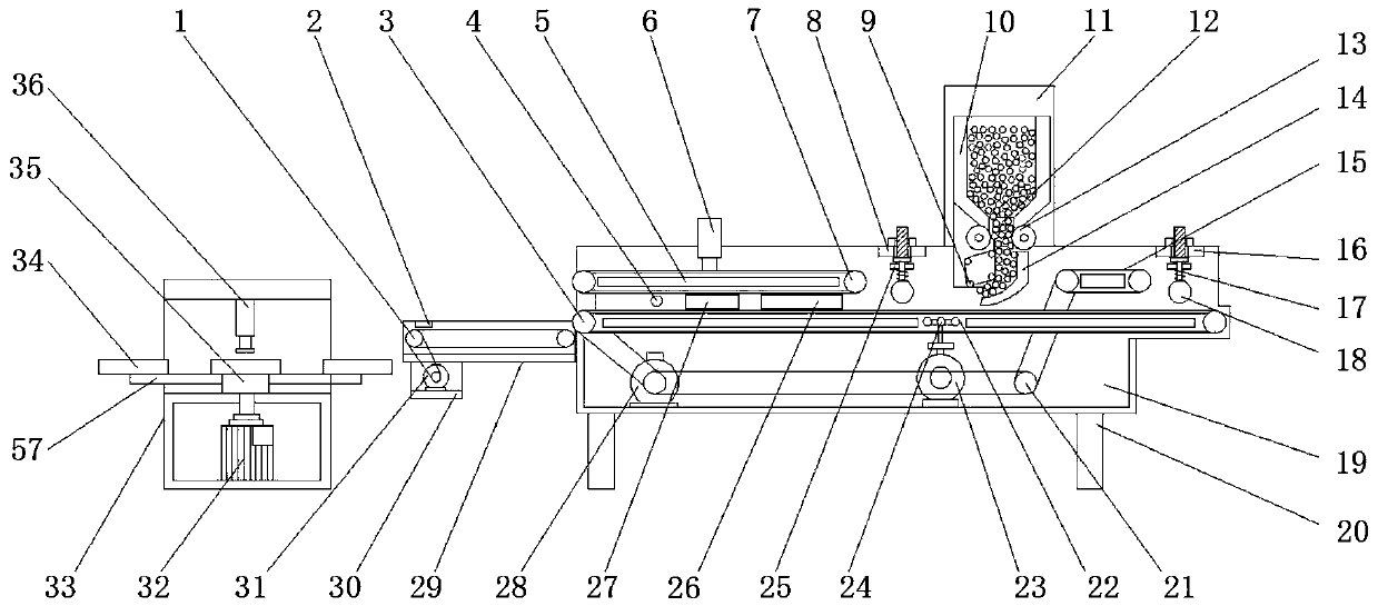
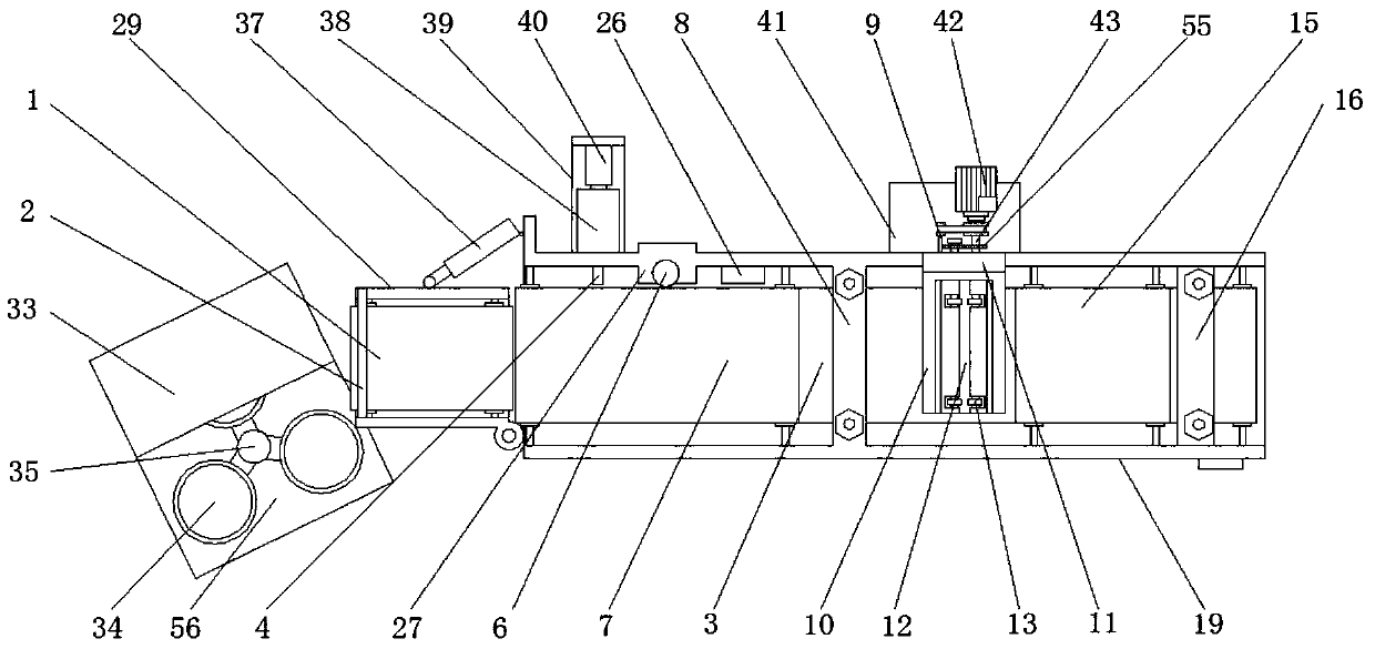
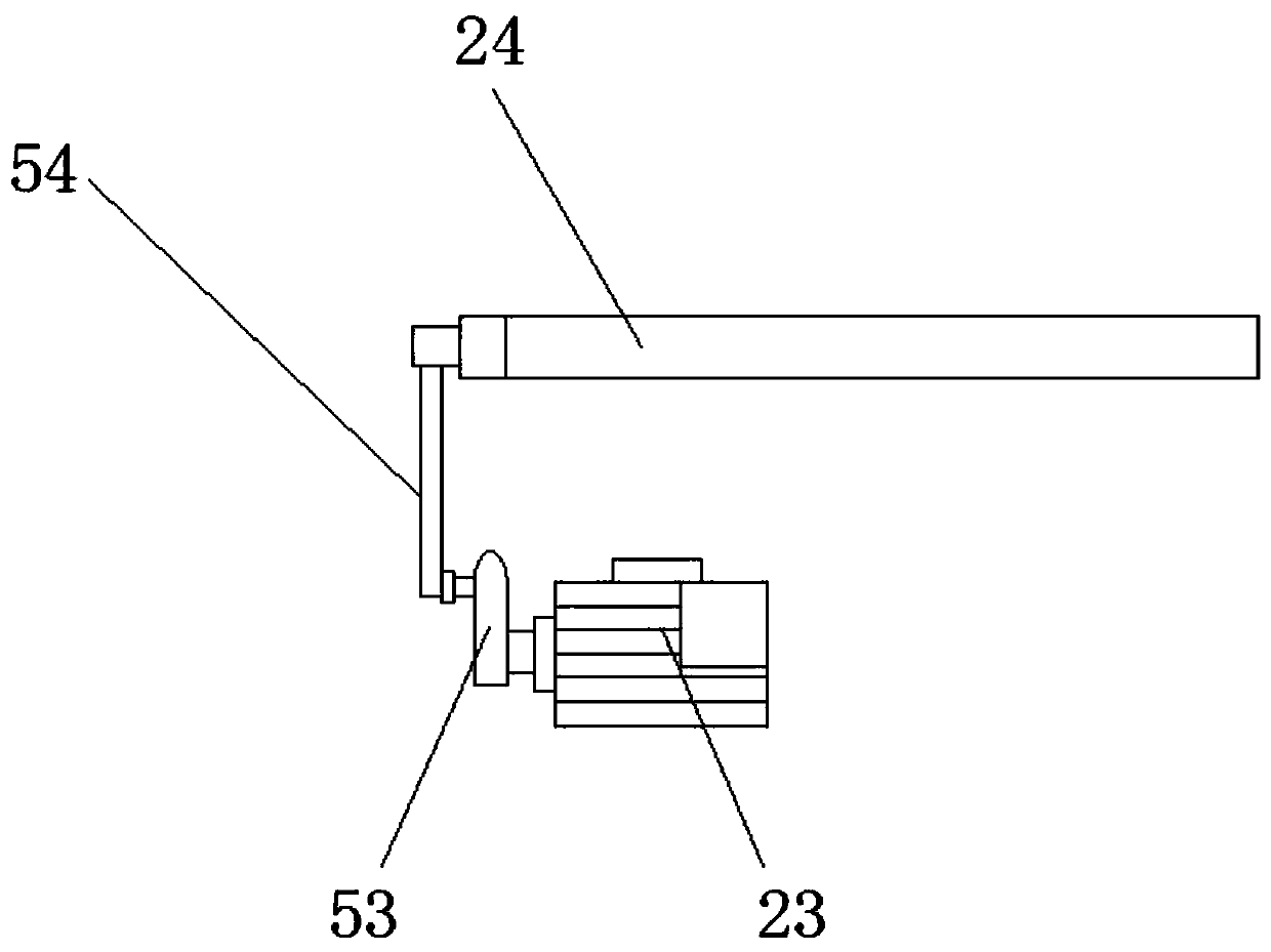
[0027] See Figure 1-7 , The present invention provides an embodiment: a plastic inner ring sweeping brush sheet casting process production line, including a guide conveyor belt 1, a main conveyor belt 3, a first extrusion conveyor belt 7, a second extrusion conveyor belt 15, and a mounting seat 19 And the die-cast seat 33, the four corners of the bottom of the mounting seat 19 are all fixed with support columns 20, the inner side of the mounting seat 19 is installed with the main conveyor belt 3, the top end of the mounting seat 19 is welded with a first fixing plate 16, the mounting seat A second fixing plate 8 is welded at the middle position of the top of 19. Both ends of the second fixing plate 8 and the first fixing plate 16 are equipped with adjusting bolts 45. One end of the adjusting bolt 45 penetrates the first fixing plate 16 and the second fixing plate 16 respectively. The fixing plate 8, and between the first fixing plate 16 and the two end adjusting bolts 45 on the second fixing plate 8, a mounting plate 25 is fixed, and a squeeze roller 18 is installed under the mounting plate 25. Both ends are fixed with a first connecting rod 46 penetrating the mounting plate 25, and a compression spring 17 is installed outside the first connecting rod 46 between the squeeze roller 18 and the mounting plate 25, and the first fixing plate 16 is close to the second fixing plate A second squeezing conveyor belt 15 is installed inside the mounting seat 19 above the main conveyor belt 3 on one side of the 8 side. A support plate 11 is welded on the top side of the mounting seat 19 between the second squeezing conveyor belt 15 and the second fixing plate 8. The support plate A feeding hopper 10 located directly above the main conveyor belt 3 is fixed on the inside of the 11, and a discharge port 12 is provided at the bottom of the feeding hopper 10. Both sides of the discharge port 12 are provided with a first rotating shaft 43, and the first rotating shaft 43 is installed For the runner 13, one ends of the first rotating shafts 43 on both sides extend to the outside of the support plate 11 and are fixed with gears 55, and the two gears 55 are meshed. The outer wall of the mounting seat 19 at the position of the support plate 11 is fixed with a first Place the plate 41. A first motor 42 is installed on the top of the first placement plate 41. The output end of the first motor 42 is fixedly connected to a first rotating shaft 43. The inner side of the support plate 11 directly below the hopper 10 is fixed obliquely downward. The guide plate 14, the inner side of the support plate 11 on the side of the guide plate 14 is evenly arranged with four second rotating shafts 9 with a chain wrapped between the four second rotating shafts 9, and one end of the second rotating shaft 9 extends to the support The outside of the plate 11 is connected to the output end of the first motor 42 through a pulley mechanism. The shape of the chain wrapped on the outside of the second shaft 9 near the guide plate 14 is consistent with the shape of the inner wall of the guide plate 14. The main conveyor belt 3 at the position between the material plate 14 and the second fixed plate 8 is provided with a movable groove 22 inside. The inside of the movable groove 22 is provided with a flapping rod 24. A cam is installed at the inner bottom of the mounting seat 19 directly below the flapping rod 24 The output end of the motor 23 and the cam motor 23 is equipped with a cam 53. One end of the cam 53 and the tapping rod 24 is hinged with a hinge rod 54. A second motor 28 is installed on one side of the inner bottom of the mounting seat 19, the output end of the second motor 28 It is connected to the main conveyor belt 3 through a pulley mechanism. The other side of the inner bottom end of the mounting seat 19 is equipped with a transmission shaft 21. The transmission shaft 21 is connected to the output end of the second motor 28 through the pulley mechanism, and the transmission shaft 21 is connected to the second extruder. Press belt 15 Connected by a pulley mechanism, a first squeeze conveyor belt 7 is installed inside the mounting seat 19 on the side of the second fixing plate 8 away from the hopper 10, and the first squeeze conveyor belt 7 and the main conveyor belt 3 are connected by a pulley mechanism, and The inside of the first squeeze conveyor belt 7, the second squeeze conveyor belt 15 and the main conveyor belt 3 are all provided with a fixed baffle 5, and the inner side of the mounting seat 19 on one side of the first squeeze conveyor belt 7 is fixed with a hot melt frame 26. An infrared hot melt tube 52 is installed at the bottom of the inner part of the 26. A repair frame 27 is fixed on the inside of the mounting seat 19 on the side of the hot melt frame 26 far away from the second fixing plate 8. The top of the repair frame 27 is equipped with a cylinder 6 and a cylinder 6. The output end extends to the inside of the repair frame 27 and is fixed with a movable plate 47. One side of the bottom of the movable plate 47 is installed with a cutter 51 parallel to the first squeezing conveyor 7, and the cutter 51 is close to the first squeezing conveyor 7. A limit plate 50 is installed under the movable plate 47 on one side. Both ends of the top of the limit plate 50 are welded with a second connecting rod 48 that penetrates the movable plate 47, and the second connection between the limit plate 50 and the movable plate 47 A buffer spring 49 is installed on the outside of the rod 48. A second placement plate 39 is fixed on the outer wall of the mounting seat 19 on the side of the repair frame 27 away from the hot melt frame 26. A glue storage tank 38 is installed on the top of the second placement plate 39 to store glue. One end of the tank 38 is provided with a rubber outlet pipe 4 extending to the inside of the mounting seat 19, a first electric telescopic rod 40 is installed on the top of the second placement plate 39 at the other end of the glue storage tank 38, and the output end of the first electric telescopic rod 40 extends To the inside of the glue storage tank 38 and installed with a piston 44, a mounting frame 29 is hinged on the mounting seat 19 at one end of the main conveyor belt 3, and a guide conveyor belt 1 is installed on the inner side of the mounting frame 29. A protective plate 2 is fixed on the top of the frame 29, and a second electric telescopic rod 37 is hinged between the outer side wall on the side of the mounting frame 29 away from the hinge axis and the mounting seat 19, and a third placing plate 30 is fixed at the bottom of the mounting frame 29. A third motor 31 is installed on the inside of the three placement plate 30, and the output end of the third motor 31 is connected to the guide conveyor belt 1 through a pulley mechanism. One side of the mounting seat 19 is provided with a casting seat 33, and the middle of the casting seat 33 There is an operating platform 56 at the position. A fourth motor 32 is installed inside the casting seat 33. The output end of the fourth motor 32 extends above the operating platform 56 and is installed with a rotating seat 35. The outer wall of the rotating seat 35 passes The connecting block 57 is uniformly fixed with the casting plate 34, the casting plate 34 uniformly fixed by the connecting block 57 on the outer side wall of the rotating seat 35 is arranged in a regular triangle shape, and the top of the casting seat 33 above the operating platform 56 is installed with the casting plate 34 Matched hydraulic cylinder 36.
[0028] Working principle: When the production of sweeping brushes is required, manually place the brush filaments inside the feeding hopper 10, and turn the adjusting bolt 45 to adjust the height of the squeeze roller 18, so that the external power supply of the equipment is energized, and the first motor 42 rotates , The first rotating shaft 43 on the bottom side of the hopper 10 is driven to rotate, and under the action of the gear 55, the runners 13 on the first rotating shaft 43 on both sides of the bottom of the hopper 10 rotate in the opposite direction, thereby turning the inside of the hopper 10 The brush filaments are conveyed from the position of the discharge port 12. While the first motor 42 rotates, the second rotating shaft 9 is driven to rotate through the pulley mechanism, and the outside between the second rotating shafts 9 is wrapped with a chain, which can make the second The rotating shaft 9 drives the chain to rotate along the outer side of the four second rotating shafts. Due to the squeezing and friction of the chain, the brush filaments are evenly transported on the guide plate 14 to the top of the main conveyor belt 3, and the first motor 42 is controlled to stop Rotate to stop conveying the brush filaments to the upper surface of the main conveyor belt 3 and control the length of the brush filament arrangement. The second motor 28 rotates to make the main conveyor belt 3 convey the brush filaments. The cam motor 23 rotates to drive the hinged hinge rod. 54 moves up and down, so that the flapping rod 24 moves up and down inside the movable groove 22, imitating the flapping action of the human body, causing the main conveyor belt 3 to vibrate, sorting the brush filaments on the main conveyor belt 3, and maintaining the alignment on the conveyor belt The brush filaments are arranged neatly. When the brush filaments are transported to the upper surface of the main conveyor belt 3 at the position of the movable groove 22, when the brush filaments are transported to the bottom of the squeezing roller 18 between the hopper 10 and the first squeezing conveyor belt 7, the squeezing The roller 18 squeezes the brush filaments to keep the thickness of the brush filaments consistent. The brush filaments after passing through the squeeze roller 18 enter between the main conveyor belt 3 and the first squeezing conveyor belt 7, and pass through the inner side of the hot melt frame 26 in turn. The infrared hot-melt tube 52 heat-melts one end of the brush wire, and the hot-melted end of the brush wire is transported to the inside of the repair frame 17. The cylinder 6 pushes the movable plate 47 down, so that the limit plate 50 first contacts the brush wire. And under the action of the buffer spring 49, the brush wire is squeezed and limited to avoid the continuous extrusion of the cylinder 6 after the brush wire is displaced, so that the cutter 51 repairs the hot melted brush wire. The wire moves to the position of the hose 4, and the first electric telescopic rod 40 moves a fixed amount of length. The piston 44 uses the piston 44 to extrude the glue in the glue tank 38 to coat one end of the brush wire, and the glued brush wire is transported To the top of the guiding conveyor belt 1, the first motor 31 rotates, driving the guiding conveyor belt 1 to rotate, conveying the material to the end close to the protective plate 2, and the protective plate 2 prevents the brush wire from falling, and the second electric telescopic rod 37 works, Rotate the mounting frame 29 to a certain angle to move the brush wire on the guide conveyor 1 to the position of the operating platform 56, which is convenient for workers to take and place it inside the casting plate 34. The fourth motor 32 rotates one third The round angle drives the casting plate 34 under the hydraulic cylinder 36 to cyclically replace, and the hydraulic cylinder 36 is used to cast and press the brush wire that moves to the casting plate 34 under the hydraulic cylinder 36. At this time, the worker is convenient for casting The brush piece on the die-cast plate 34 is removed.
[0029] For those skilled in the art, it is obvious that the present invention is not limited to the details of the foregoing exemplary embodiments, and the present invention can be implemented in other specific forms without departing from the spirit or basic characteristics of the present invention. Therefore, from any point of view, the embodiments should be regarded as exemplary and non-limiting. The scope of the present invention is defined by the appended claims rather than the foregoing description, and therefore it is intended to fall within the claims. All changes within the meaning and scope of equivalent elements of are included in the present invention. Any reference signs in the claims should not be regarded as limiting the claims involved.