Electrostatic controllable abrasive grain flow machining removal amount detection device and detection method

A detection method and abrasive particle flow technology, applied in the direction of measuring devices, used abrasive processing devices, metal processing equipment, etc., can solve the problem that the processing quality is not easy to improve, the process parameters are difficult to control, and the Preston equation is not applicable, etc. problem, to achieve the effect of improving the surface of the substrate with less, high-efficiency ultra-smooth surface processing

Pending Publication Date: 2019-04-02
ZHEJIANG UNIV OF TECH
View PDF9 Cites 3 Cited by
  • Summary
  • Abstract
  • Description
  • Claims
  • Application Information

AI Technical Summary

Problems solved by technology

[0003] The purpose of the present invention is to solve the shortcomings of the existing electrostatic controllable abrasive flow processing, such as the inapplicability of the Preston equation, the difficulty in improving the processing efficiency and processing quality, and the difficulty in controlling the process parameters, etc., and provides an electrostatic controllable abrasive flow processing Removal amount detection device and detection method, the method is suitable for the process optimization of precision automatic grinding and polishing of workpiece surfaces such as optical elements and amorphous film substrates in the electrostatic controllable abrasive flow processing method based on the charge tip aggregation effect

Method used


Image

  • Electrostatic controllable abrasive grain flow machining removal amount detection device and detection method
  • Electrostatic controllable abrasive grain flow machining removal amount detection device and detection method
  • Electrostatic controllable abrasive grain flow machining removal amount detection device and detection method

Examples


Embodiment Construction

[0026] The present invention will be further described below in conjunction with accompanying drawing:

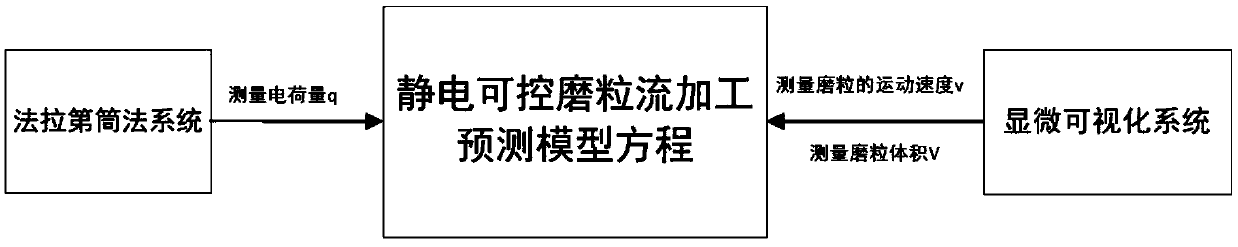
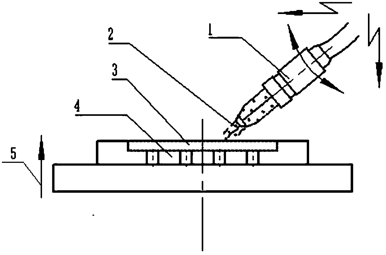
[0027] Such as Figure 1-6As shown in , an electrostatic controllable abrasive flow processing removal amount detection device includes an abrasive flow processing device, a Faraday cylinder method system and a microscopic visualization system. The abrasive flow processing system includes a high-voltage electrostatic generator 1, a Die adsorption platform 4, external electric field 5, abrasive particle flow 2 and workpiece 3, workpiece 3 is fixed by matching mold adsorption platform 4, abrasive particle flow 2 is launched to the surface of workpiece 3 after passing through high-voltage electrostatic generator 1 for abrasive flow processing, The external electric field 5 is directly loaded on the entire mold matching adsorption platform 4 and the workpiece 3 .

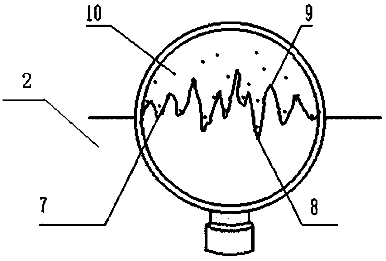
[0028] When the abrasive flow processing device is working, the actual processing surface 7 of the workpiece 3 is...


PUM


Abstract

The invention discloses an electrostatic controllable abrasive grain flow machining removal amount detection device and detection method. The electrostatic controllable abrasive grain flow machining removal amount detection device comprises a grinding grain flow machining device, a faraday cylinder method system and a microscopic visualization system, wherein the grinding grain flow machining system comprises a high-voltage electrostatic generator, a mold distribution adsorption platform, an additional electric field, an abrasive grain flow and a workpiece, the workpiece is fixed through the mold distribution adsorption platform, the abrasive grain flow is transmitted to the surface of the workpiece after passing through the high-voltage electrostatic generator and then is subjected to abrasive grain flow machining, and the additional electric field is directly loaded on the whole mold distribution adsorption platform and the workpiece. The invention provides an electrostatic controllable abrasive grain flow machining method empirical prediction model equation suitable for a charge tip aggregation effect, the correlation between the charged charge measurement of the abrasive grainsis solved through the faraday cylinder system design, and a theoretical basis for selecting the cutting acting force of the appropriate abrasive grains and the workpiece is provided.

Description

technical field [0001] The invention relates to the technical field of ultra-precision machining, and more specifically relates to a detection device and a detection method for the removal amount of electrostatic controllable abrasive flow processing. Background technique [0002] Fluid polishing is one of the important means to obtain ultra-smooth surfaces, and has attracted much attention from researchers. Float polishing, bath polishing, magnetic fluid polishing, electrorheological fluid polishing, magnetorheological fluid polishing, fluid vibration polishing, ultrasonic magnetorheological composite polishing, jet polishing, dynamic pressure suspension polishing, dielectrophoretic polishing, gas-liquid solid three Technologies such as phase abrasive flow polishing came into being. Previous studies have shown that the formation of an ultra-smooth surface with little damage depends on the contact state between the abrasive grains and the workpiece surface. Fluid polishing...

Claims


Application Information

Patent Timeline
Patent Type & Authority Applications(China)
IPC IPC(8): B24C1/08B24C9/00G01N15/10G06F17/50
CPCG01N15/10B24C1/08B24C9/00G01N2015/1075G06F30/17G06F30/20
Inventor 蔡东海金明生王扬渝屠立群齐欢陈珍珍
Owner ZHEJIANG UNIV OF TECH
Why Eureka
Try Eureka