A mask and its manufacturing method

A mask and substrate technology, applied in the field of mask, can solve the problems of increasing the reject rate, affecting the production accuracy of products, alignment deviation, etc., and achieving the effects of reducing the reject rate, the number of exposures, and the number of sheets

Active Publication Date: 2022-02-18
深圳市龙图光罩股份有限公司
View PDF6 Cites 0 Cited by
  • Summary
  • Abstract
  • Description
  • Claims
  • Application Information

AI Technical Summary

Problems solved by technology

[0004] However, in actual production, there will be many factors that cause alignment deviations, for example, the expansion and contraction of graphics caused by environmental deviations (such as thermal expansion of graphics caused by temperature) during the production of each sub-pattern mask, and the expansion of each sub-pattern mask. The equipment deviation caused by the production of different equipment for the template, the graphic expansion and contraction caused by the environmental deviation of different sub-masks due to different usage times during product production, and the alignment between multiple sub-graphics caused by the alignment accuracy of the product production equipment Deviations, etc., affect the accuracy of product production and increase the scrap rate

Method used


Image

  • A mask and its manufacturing method
  • A mask and its manufacturing method
  • A mask and its manufacturing method

Examples


Embodiment 1

[0018] Embodiment 1 provides a mask.

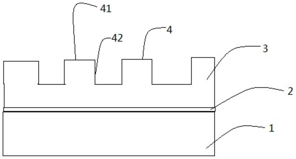
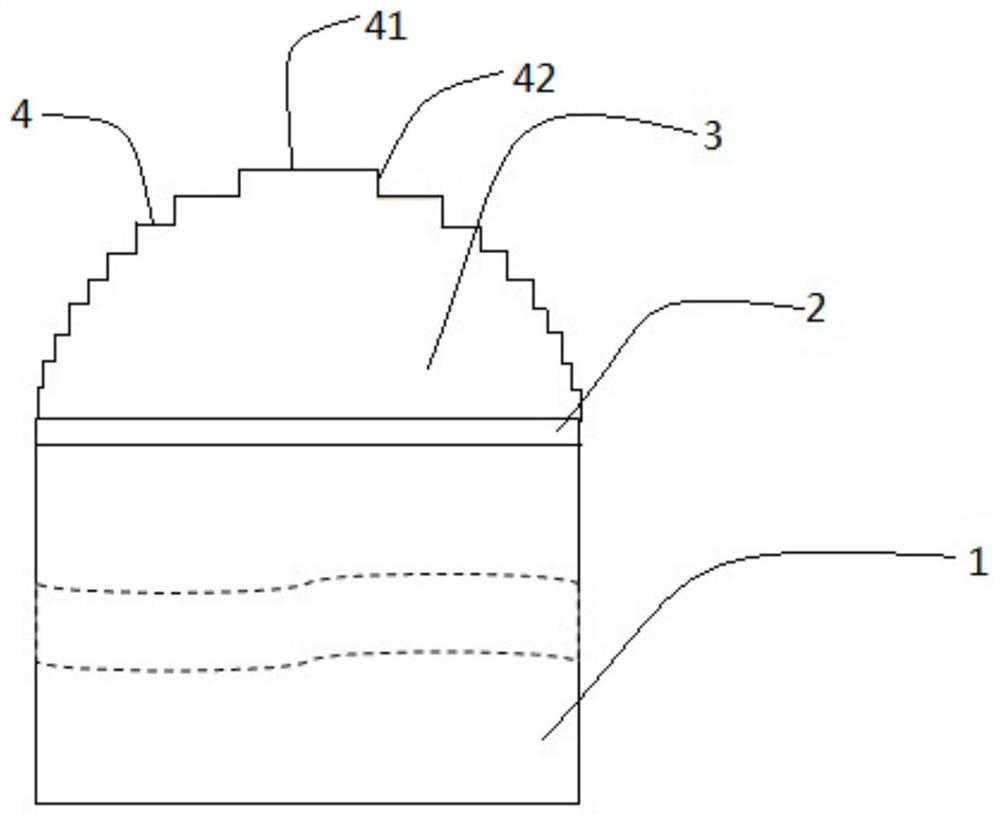
[0019] Please refer to figure 1 , in one embodiment, the mask plate includes: a substrate 1 and a photoresist layer 3, the photoresist layer 3 is arranged on the substrate 1, the side of the photoresist layer 3 in contact with the product is a top wall 4, and the top wall 4 has at least two Two bonding surfaces 41 parallel to the substrate 1 have different heights. Adjacent bonding surfaces 41 are connected by a connecting wall 42 perpendicular to the substrate 1. The top wall 4 is used to record three-dimensional structure information. The height of the bonding surface 41 refers to the vertical distance from the bonding surface 41 to the substrate 1 .

[0020] Please continue to refer figure 1 , the mask plate further includes a light-blocking metal layer 2 , and the light-blocking metal layer 2 is disposed between the substrate 1 and the photoresist layer 3 .

[0021] Specifically, the substrate 1 , the light-blocking metal layer 2 a...

Embodiment 2

[0027] This embodiment provides a method for fabricating a mask, specifically a method for fabricating the mask in Embodiment 1.

[0028] The software and hardware required to make a mask are:

[0029] The raw material board, the raw material board includes a substrate, a light-blocking metal layer and a photoresist layer (unprocessed), and the thickness of the photoresist layer 3 is between 200nm and 10000nm. A direct-write lithography machine with repeatable exposure that can change parameters such as focal depth and energy, and a software server with AUTOCAD installed and capable of processing DWG, DXF and other formats.

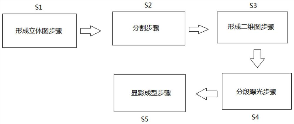
[0030] Please refer to image 3 , Figure 4 and Figure 5 , in one embodiment, the manufacturing method includes:

[0031] In step S1 of forming a stereogram, the shape of the product matches the shape of the photoresist layer 3 , and a three-dimensional stereogram of the photoresist layer 3 of the mask plate to be produced is formed according to the sh...


PUM

PropertyMeasurementUnit
thicknessaaaaaaaaaa
thicknessaaaaaaaaaa
thicknessaaaaaaaaaa

Abstract

The present application discloses a mask plate and a manufacturing method thereof, including: a substrate and a photoresist layer, the photoresist layer is arranged on the substrate, the side of the photoresist layer in contact with the product is a top wall, and the top wall has At least two bonding surfaces parallel to the substrate have different heights. Adjacent bonding surfaces are connected by a connecting wall perpendicular to the substrate. The top wall is used to record three-dimensional structure information. When it is necessary to produce a product with a multi-layer structure, the three-dimensional structure information contained in the photoresist layer can be transferred to the raw material of the product by means of electroplating, injection molding or direct embossing to complete the production of the product without using multiple masks. The template alignment overlay production avoids the deviation in the alignment overlay production, improves the precision of product production, reduces the reject rate, and reduces the number of exposures, thereby saving the process, reducing the number of sheets of the mask used, and saving costs.

Description

technical field [0001] The present application relates to the field of mask plates, in particular to a mask plate and a manufacturing method thereof. Background technique [0002] The mask plate is composed of a metal layer film or a photoresist layer film and a substrate on which information such as graphics and characters are recorded on the surface. It is widely used in molds in industries such as IC, FPD, MEMS, and optical devices. [0003] When using a mask plate to produce a product with a multi-layer structure, the overlay production is usually used to divide the total graphic information of a product into multi-layer sub-patterns according to the process requirements, and make the sub-patterns into corresponding exposure masks. Stencil (there are as many layers of masks as there are layers of sub-patterns), each mask has alignment marks, and the alignment marks on each layer of sub-patterns are overlapped according to a certain process sequence during production befo...

Claims


Application Information

Patent Timeline
Patent Type & Authority Patents(China)
IPC IPC(8): G03F1/88G03F1/80G03F1/68
CPCG03F1/68G03F1/80G03F1/88
Inventor 黄执祥侯广杰
Owner 深圳市龙图光罩股份有限公司
Why Eureka
Try Eureka