Microwave plasma vacuum coating equipment and use method

A microwave plasma and vacuum coating technology, applied in gaseous chemical plating, metal material coating process, coating, etc., can solve the problems of poor uniformity and consistency of coating, easy pollution of chemical substances to the environment, and low sedimentation rate. , to improve uniformity and consistency, improve coating production efficiency, and increase sedimentation rate

Inactive Publication Date: 2019-04-02
朱广智
View PDF5 Cites 2 Cited by
  • Summary
  • Abstract
  • Description
  • Claims
  • Application Information

AI Technical Summary

Problems solved by technology

[0003] The existing coating equipment and methods have the disadvantages of low sedimentation rate, low production efficiency, poor uniformity and consistency of the coating, poor waterproof, sweat-proof, moisture-proof, corrosion-resistant, and solvent-resistant effects of the coating, etc. The chemical used in the coating Substances, etc. are also likely to cause pollution to the environment, which does not meet the country's requirements for green development

Method used


Image

  • Microwave plasma vacuum coating equipment and use method
  • Microwave plasma vacuum coating equipment and use method

Examples


Embodiment 1

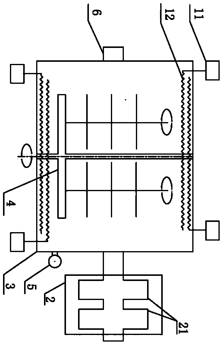
[0031] A microwave plasma vacuum coating device, comprising a microwave antenna 12, a microwave source 11, an air intake device 6, an exhaust device 2, a plasma vacuum chamber 3 and a moving device 4, the vacuum exhaust device 2 is arranged on the plasma vacuum chamber 3 The outside is connected to the cavity through pipes, the microwave antenna 12 and the moving device 4 are arranged inside the plasma vacuum cavity 3, and the microwave source 11 is arranged outside the cavity and connected to the microwave antenna in the cavity.

[0032] The microwave source 11 is placed outside the cavity 3, the microwave antenna 12 is placed inside the cavity 3 and connected with the external microwave source 11, and there are two pairs of microwave antenna and microwave source.

[0033] The air intake device 6 is a channel through which external air or steam enters the cavity.

[0034] The vacuum exhaust device 2 includes a vacuum pump 21 and an exhaust pipe. The vacuum pump 21 is divided ...

Embodiment 2

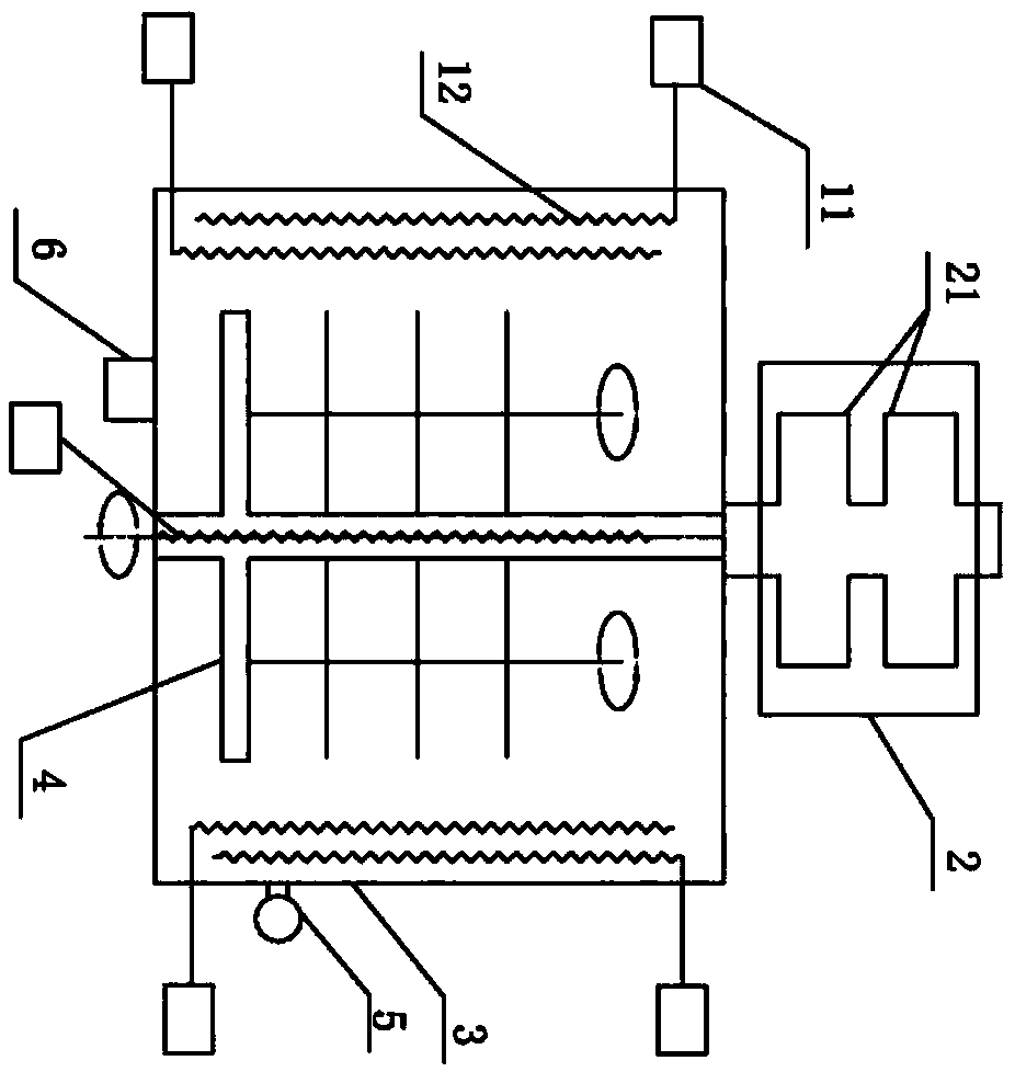
[0046] A microwave plasma vacuum coating device, comprising a microwave antenna 12, a microwave source 11, an air intake device 6, an exhaust device 2, a plasma vacuum chamber 3 and a moving device 4, the vacuum exhaust device 2 is arranged on the plasma vacuum chamber 3 The outside is connected to the cavity through pipes, the microwave antenna 12 and the moving device 4 are arranged inside the plasma vacuum cavity 3, and the microwave source 11 is arranged outside the cavity and connected to the microwave antenna in the cavity.

[0047] The microwave source 11 is placed outside the cavity 3, the microwave antenna 12 is placed inside the cavity 3 and connected with the external microwave source 11, and there are three pairs of microwave antennas and microwave sources.

[0048] The air intake device 6 is a channel through which external air or steam enters the cavity.

[0049] The vacuum exhaust device 2 includes a vacuum pump 21 and an exhaust pipe. The vacuum pump 21 is divi...


PUM

PropertyMeasurementUnit
volumeaaaaaaaaaa

Abstract

The invention discloses microwave plasma vacuum coating equipment and a use method. The equipment comprises a microwave antenna, a microwave source, an air inflow device, an air exhaust device, a plasma vacuum cavity and a moving device. The vacuum air exhaust device is arranged outside the plastic vacuum cavity and connected with the cavity through a pipeline, the microwave antenna and the movingdevice are arranged in the plasma vacuum cavity, and the microwave source is arranged outside the cavity and connected with the microwave antenna in the cavity. The use method of the equipment includes the following steps that the plasma vacuum cavity is vacuumized, and a to-be-coated product is pre-treated, coated and the like. The sedimentation rate of coating matter is increased and the coating production efficiency of the coating matter is improved with a plasma chemical vapor deposition method, the uniformity and consistency of coating are improved, meanwhile, the waterproof, sweat-proof, damp-proof, corrosion-resistant and solvent-resistant performance and other protection effects of coatings are also improved, and the microwave plasma vacuum coating equipment can be used for the occasions of coating such as various PCBs, PCBAs, electronic products, electric appliance parts, electronic semi-finished products, metal, electronic components, semiconductors, integrated circuit boards and plastic products.

Description

technical field [0001] The invention relates to the technical field of plasma chemical vapor deposition, in particular to a microwave plasma vacuum coating device and a use method. Background technique [0002] Plasma Enhanced Chemical Vapor Deposition PECVD: It uses microwave or radio frequency to ionize the gas containing the constituent atoms of the film to form plasma locally, and the plasma is very chemically active and easy to react, depositing the desired film on the substrate . In order to enable the chemical reaction to proceed at a lower temperature, the activity of the plasma is used to promote the reaction, so this CVD is called plasma-enhanced chemical vapor deposition (PECVD). Experimental mechanism: The gas containing the constituent atoms of the film is locally formed into plasma by means of microwave or radio frequency, and the plasma is chemically active and easily reacts to deposit the desired film on the substrate. [0003] The existing coating equipmen...

Claims


Application Information

Patent Timeline
Patent Type & Authority Applications(China)
IPC IPC(8): C23C16/511C23C16/458C23C16/513C23C16/517C23C16/52C23C16/455
CPCC23C16/45523C23C16/458C23C16/511C23C16/513C23C16/517C23C16/52
Inventor 朱广智
Owner 朱广智
Why Eureka
Try Eureka