Electrical automatic equipment overhauling protection device

A technology for electrical automation and equipment maintenance. It is applied to the device for coating liquid on the surface, special surface, coating, etc. It can solve the problem of scratches and damage on the surface of the rubber roller, affect the service life of the rubber roller, and increase the operating cost of the factory. and other problems, to achieve the effect of not easy to delaminate, moderate viscosity, and reduce operating costs

Inactive Publication Date: 2019-04-05
IANGSU COLLEGE OF ENG & TECH
View PDF10 Cites 2 Cited by
  • Summary
  • Abstract
  • Description
  • Claims
  • Application Information

AI Technical Summary

Problems solved by technology

[0002] In the process of overhauling electrical automation equipment, it is generally necessary to use protective devices to protect the components on the electrical automation equipment, which can prevent the components on the electrical automation equipment from being damaged during the maintenance process. Electrical automation gluing equipment is a kind of precision equipment. During maintenance, it is necessary to fix the upper gluing roller to prevent the gluing roller from being scratched and damaged. However, the existing electrical automation gluing equipment is not easy to fix the upper gluing roller due to its shape characteristics. At the same time, its large volume occupies a large area of ​​the factory building. In order to save the area inside the factory building, some factories will install one side of the electrical automation gluing equipment close to the wall of the factory building, resulting in the coating on the upper part of the electrical automation gluing equipment. It is more inconvenient to fix the rubber roller, and it is easy to cause the surface of the rubber roller to be scratched and damaged during the maintenance of the electrical automation gluing equipment, which seriously affects the service life of the rubber roller, which in turn leads to an increase in the operating cost of the factory. , proposes a maintenance protection device for electrical automation equipment

Method used


Image

  • Electrical automatic equipment overhauling protection device
  • Electrical automatic equipment overhauling protection device
  • Electrical automatic equipment overhauling protection device

Examples


Embodiment 1

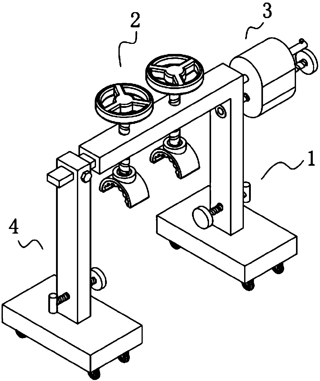
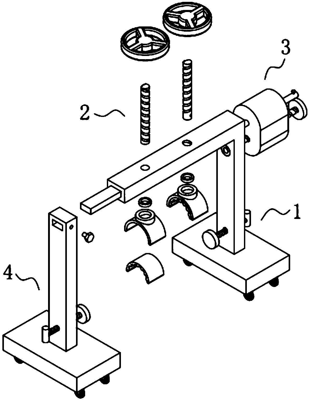
[0051] A maintenance protection device for electrical automation equipment, such as Figure 1-2 As shown, it includes a first support unit 1 and two groups of compression units 2, and the two groups of compression units 2 are installed on the upper part of the first support unit 1;

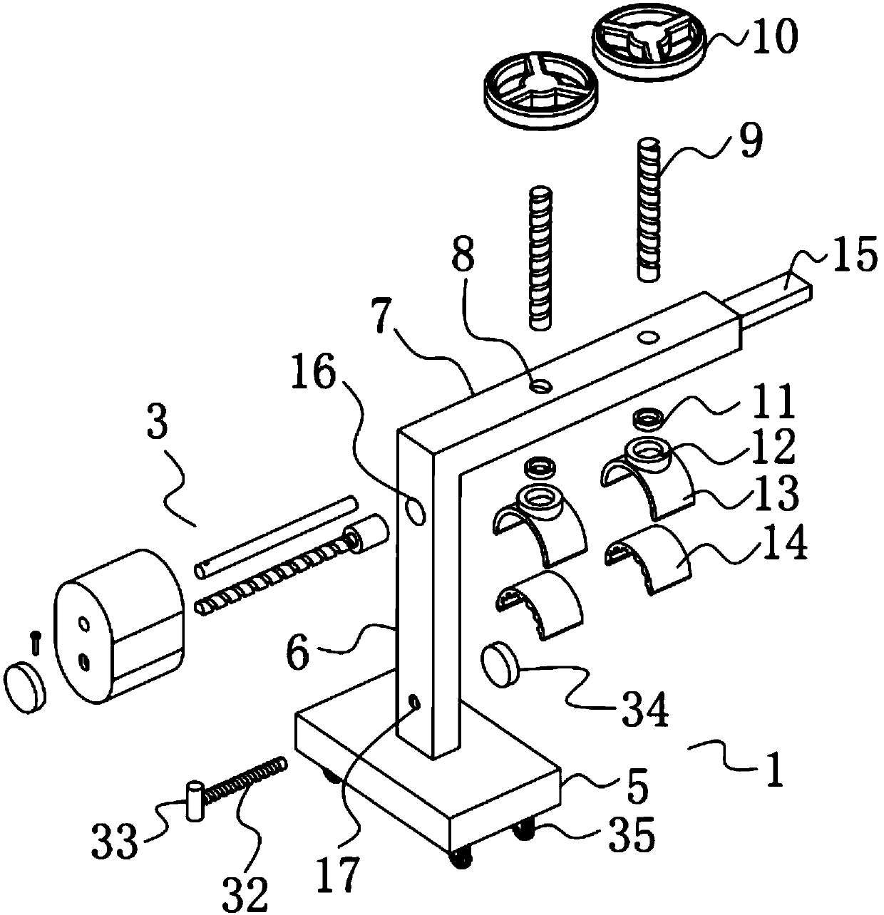
[0052] Such as image 3 As shown, the first support unit 1 includes a first base 5, a first support column 6 vertically and fixedly installed on the upper part of the first base 5, and a beam 7 fixedly installed on the upper end of the first support column 6, Two first installation holes 8 are symmetrically opened on the beam 7;

[0053] Such as image 3 As shown, each set of the pressing unit 2 includes a first threaded rod 9 vertically screwed inside the first mounting hole 8, a hand plate 10 fixedly installed on the upper end of the first threaded rod 9 and a The first rolling bearing 11 is fixedly set on the connection seat 12 outside the bottom end of the first threaded rod 9 and the arc-s...

Embodiment 2

[0068] The difference from Example 1 is that the surfaces of the first base 5 and the second base 26 are provided with a protective layer, and the protective layer is prepared by the following method:

[0069] Take the following raw materials and weigh them by weight: 20 parts of epoxy resin, 8 parts of mica powder, 11 parts of titanium dioxide powder, 12 parts of polytetrafluoroethylene, 12 parts of graphite powder, 8 parts of talcum powder, 2 parts of film-forming aids, 2 parts of agent, 1 part of defoamer and 30 parts of methanol;

[0070] S1. Add the weighed film-forming aid, accelerator, defoamer and methanol into the mixer and stir for 20min at a stirring speed of 600r / min to prepare a mixed solution;

[0071] S2, adding epoxy resin, mica powder, titanium dioxide powder, polytetrafluoroethylene, graphite powder and talcum powder into a pulverizer for pulverization to obtain a mixed powder material;

[0072] S3. Add the mixed solution prepared in step S1 and the mixed po...

Embodiment 3

[0081] The difference with embodiment 2 is the preparation of protective layer, and its specific preparation method is as follows:

[0082] Take the following raw materials and weigh them by weight: 25 parts of epoxy resin, 10 parts of mica powder, 13 parts of titanium dioxide powder, 14 parts of polytetrafluoroethylene, 14 parts of graphite powder, 9 parts of talcum powder, 3 parts of film-forming aids, 3 parts of agent, 2 parts of defoamer and 35 parts of methanol;

[0083] S1. Add the weighed film-forming aid, accelerator, defoamer and methanol into the mixer and stir for 25min at a stirring speed of 700r / min to prepare a mixed solution;

[0084] S2, adding epoxy resin, mica powder, titanium dioxide powder, polytetrafluoroethylene, graphite powder and talcum powder into a pulverizer for pulverization to obtain a mixed powder material;

[0085] S3. Add the mixed solution prepared in step S1 and the mixed powder material prepared in step S2 to the reactor and stir for 25 min...


PUM


Abstract

The invention discloses an electrical automatic equipment overhauling protection device. A first supporting unit and two pressing units are included. The two pressing units are arranged at the upper portion of the first supporting unit. The first supporting unit comprises a first base, a first supporting column vertically and fixedly arranged at the upper portion of the first base, and a beam fixedly arranged at the upper end of the first supporting column, and two first installing holes are symmetrically formed in the beam. The electrical automatic equipment overhauling protection device caneffectively prevent gluing roller rotation, the surfaces of gluing rollers can be prevented from being scratched during gluing roller overhauling, the gluing rollers can be prevented from being damaged, and accordingly, the running cost of the factory is reduced. Through a prepared protection layer, the corrosion resistance, anti-static performance, dustproof performance and the anti-aging performance of a first base and a second base can be effectively improved, the service life of the first base and the second base can be effectively prolonged, static electricity can be prevented, the situation that static electric exists in the gluing rollers, and gluing is influenced can be effectively prevented, dust is not prone to being stained on the surface of the first base or the surface of thesecond base, the dustproof effect is good, and cleaning is convenient.

Description

technical field [0001] The invention relates to the technical field of electric automation, more specifically, it relates to a maintenance protection device for electric automation equipment. Background technique [0002] In the process of overhauling electrical automation equipment, it is generally necessary to use protective devices to protect the components on the electrical automation equipment, which can prevent the components on the electrical automation equipment from being damaged during the maintenance process. Electrical automation gluing equipment is a kind of precision equipment. During maintenance, it is necessary to fix the upper gluing roller to prevent the gluing roller from being scratched and damaged. However, the existing electrical automation gluing equipment is not easy to fix the upper gluing roller due to its shape characteristics. At the same time, its large volume occupies a large area of ​​the factory building. In order to save the area inside the f...

Claims


Application Information

Patent Timeline
Patent Type & Authority Applications(China)
IPC IPC(8): B05C1/08B05D5/00B05D5/12B05D7/24
CPCB05C1/08B05D5/00B05D5/12B05D7/24B05D2504/00B05D2601/20B05D2601/24B05D2602/00
Inventor 师阳
Owner IANGSU COLLEGE OF ENG & TECH
Why Eureka
Try Eureka