Laser overlaying method for engine valve conical surfaces

A technology of engine valve and laser surfacing welding, applied in the field of laser surfacing welding, which can solve the problems of low utilization rate of surfacing welding powder, increased heat input, high operating cost, etc., achieve stable characteristics, prevent pores from forming, and eliminate slag inclusions Effect

Inactive Publication Date: 2019-04-05
HUAI JI DENG YUE VALVE CO LTD
View PDF8 Cites 4 Cited by
  • Summary
  • Abstract
  • Description
  • Claims
  • Application Information

AI Technical Summary

Problems solved by technology

[0005] At present, there are mainly three surfacing welding methods in the world. The first one is the traditional arc powder surfacing technology. Due to the influence of the arc blowing force, it is difficult to achieve the goals of high efficiency and low dilution rate at the same time. In order to improve efficiency, it will inevitably lead to heat input. increase, resulting in increased penetration of the base material, decreased performance of the surfacing layer, and greater tensile thermal stress
The second is the powder surfacing technology based on the plasma arc-based high-energy-density heat source, which is also the surfacing technology currently used for valves. This technology has a low dilution rate (5% to 10%), but the surfacing efficiency is low. , After surfacing welding, the machining allowance is large, the surfacing layer is difficult to process, the utilization rate of surfacing welding powder is not high

Method used


Image

  • Laser overlaying method for engine valve conical surfaces
  • Laser overlaying method for engine valve conical surfaces
  • Laser overlaying method for engine valve conical surfaces

Examples


Embodiment Construction

[0038] The preferred embodiments of the present invention will be described below in conjunction with the accompanying drawings. It should be understood that the preferred embodiments described here are only used to illustrate and explain the present invention, and are not intended to limit the present invention.

[0039] In the description of the present invention, it should be noted that the terms "center", "upper", "lower", "left", "right", "vertical", "horizontal", "inner", "outer" etc. The indicated orientation or positional relationship is based on the orientation or positional relationship shown in the drawings, and is only for the convenience of describing the present invention and simplifying the description, rather than indicating or implying that the referred device or element must have a specific orientation, or in a specific orientation. construction and operation, therefore, should not be construed as limiting the invention. In addition, the terms "first", "secon...


PUM


Abstract

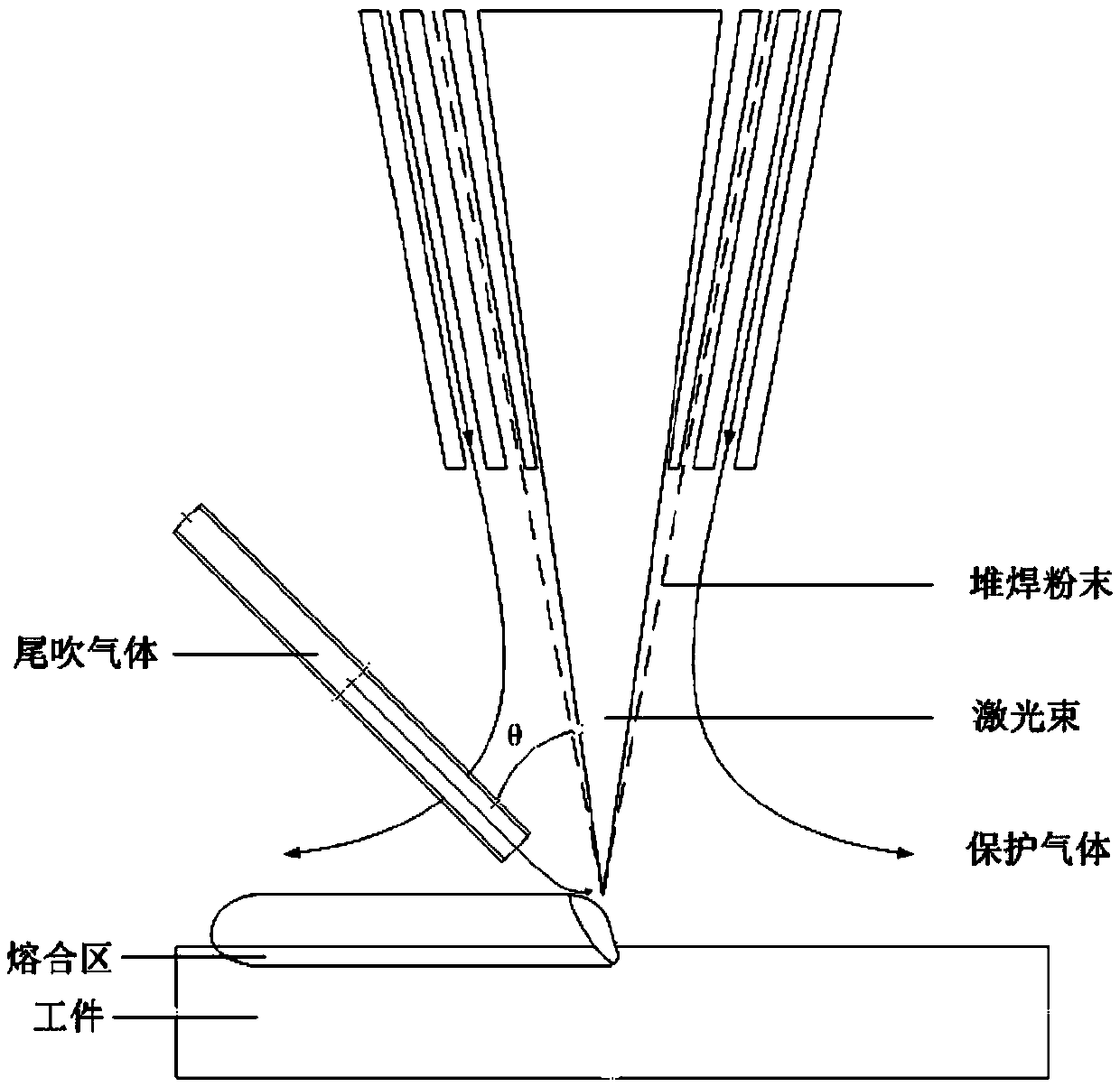
The invention discloses a laser overlaying method for engine valve conical surfaces. Valve workpieces to be overlaid are formed through machining, and are preheated in a heat treatment furnace; the preheating temperature is 200-300 DEG C; the preheating time is 15-30 min; the valve workpieces to be overlaid are fixed by using a tool; the tool is mounted on a rotating shaft, and is used for drivingthe valve workpieces to be overlaid to rotate; the valve workpieces are overlaid by laser through a laser overlaying machine; due to self rotation of the valve workpieces, a scanning trajectory of laser beams emitted by the laser overlaying machine is spiral; and the laser overlaying machine comprises the following parameters: 5-8 mm of the light spot diameter, 2000-3000 W of the laser power, 5-15 mm/s of the scanning speed, 10-16 g/min of the powder feeding speed, 5-15 L/min of the flow of tail blowing gas, 5-10 L/min of the flow of protective gas, and 35-45% of the joint rate. The method not only can effectively reduce the loss of overlaying powder and increase the utilization rate of the overlaying powder, but also can effectively reduce thermal stress.

Description

technical field [0001] The invention relates to a laser surfacing method, in particular to a laser surfacing method for an engine valve conical surface. Background technique [0002] With the ever-increasing performance requirements and environmental protection requirements, the working conditions of the engine are becoming more and more complex and harsh, and the working conditions of the valves are also becoming more severe, especially the working conditions of the exhaust valve. Because the valve moves in the engine cylinder, the working condition of the valve is more complicated. The main working conditions of the cone surface of the valve disc are as follows: (1) The valve disc is in a state of rapid opening and closing, so every time it is opened and closed, the cone surface of the valve will contact the valve seat ring, and due to the explosion pressure of the gas in the cylinder, the valve will The conical surface forms an impact with the seat ring. (2) The high te...

Claims


Application Information

Patent Timeline
IPC IPC(8): B23K26/342B23K26/60B23K26/70B33Y10/00
CPCB23K26/342B23K26/60B23K26/702B33Y10/00
Inventor 孙歌梁仕勤罗华欢邓剑雄王飞华陈冠华
Owner HUAI JI DENG YUE VALVE CO LTD
Why Eureka
Try Eureka