Heat pipe type steam generator

A steam generator and heat pipe technology, applied in the field of heat pipe steam generators, can solve the problems of large volume, high flue gas content, and difficult water level control of heat pipe steam generators, achieving no explosion risk, reducing NOx content, The effect of reducing the water volume

Pending Publication Date: 2019-04-05
杭州联赫节能环保科技有限公司
View PDF1 Cites 3 Cited by
  • Summary
  • Abstract
  • Description
  • Claims
  • Application Information

AI Technical Summary

Problems solved by technology

[0004] The purpose of the present invention is to solve the problem of difficulty in controlling the water level of traditional heat pipe steam generators, easy generation of scale, and NOx in exhausted flue gas. X The problem of high content and the large volume of the heat pipe steam generator provides a heat pipe steam generator

Method used


Image

  • Heat pipe type steam generator
  • Heat pipe type steam generator
  • Heat pipe type steam generator

Examples


Embodiment 1

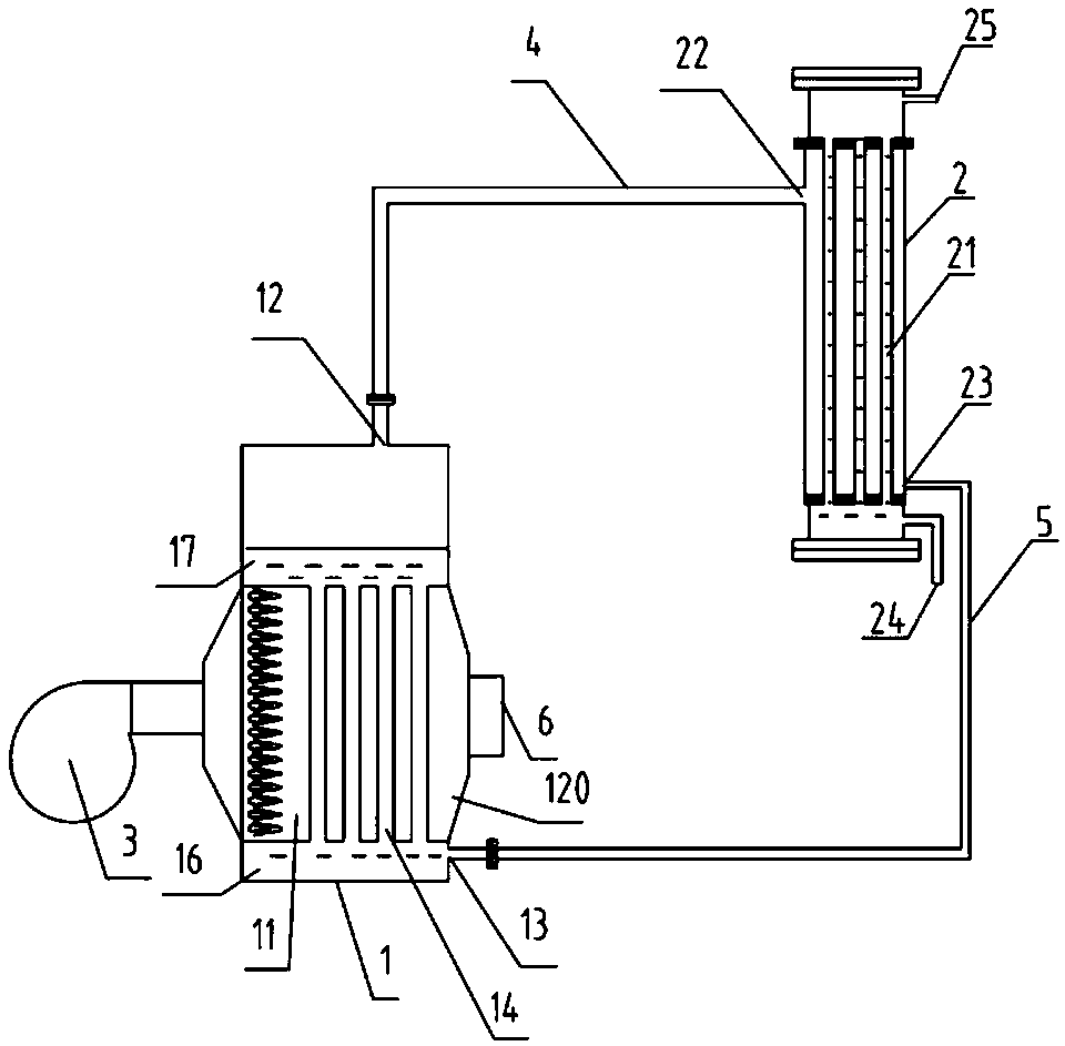
[0030] This embodiment provides a heat pipe type steam generator, such as figure 1 As shown, it includes a boiler 1, a generator 2, and a burner 3. The combustion end of the burner 3 extends into the furnace 11 of the boiler 1. The boiler 1 is connected to the generator 2. The generator 2 is provided with a heat pipe 21. A primary side channel is formed, and a secondary side channel is formed in the heat pipe 21 , and the medium in the primary side channel exchanges heat with the medium in the secondary side channel. The boiler 1 is connected to the primary side channel of the generator 2 to form a primary side circulation loop, and the primary side circulation loop is vacuum-tight. The minimum liquid level of the primary side channel is higher than the maximum liquid level of the boiler 1 .

[0031] The height difference between the liquid level in the primary channel and the boiler 1 is used to ensure that in the primary side circulation loop, the aqueous solution in the ge...

Embodiment 2

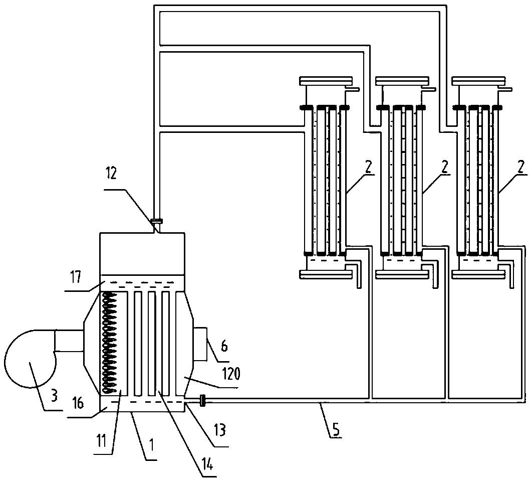
[0043] This embodiment provides a heat pipe type steam generator, such as Figure 4 , Figure 5 shown. The difference between this embodiment and the first embodiment is that the furnace body 120 is provided with a heat exchange sleeve 153 and the boiler 1 is provided with a smoke collection chamber.

[0044] The heat exchange sleeve 153 is composed of an inner tube 154 and an outer tube 155 . The inner pipe 154 is a flue gas waste heat passage, and the water flow passage is between the inner pipe 154 and the outer pipe 155 , and the flue gas waste heat passage communicates with the tail of the furnace body 120 . The high-temperature flue gas in the furnace body 120 and the flue gas in the flue gas waste heat channel jointly heat the water in the water flow channel, and make full use of the waste heat in the flue gas to ensure the evaporation of the aqueous solution in the boiler 1 .

[0045] The lower end of the outer tube 155 is the first water collecting chamber 16 , and...


PUM


Abstract

The invention relates to a steam generation device, in particular to a heat pipe type steam generator. The heat pipe type steam generator comprises a boiler, a generator body and a combustor. The combustion end of the combustor stretches into a hearth of the boiler. The boiler is connected with the generator body. A heat pipe is arranged in the generator body. A primary side channel is formed outside the heat pipe. A secondary side channel is formed in the heat pipe. Media in the primary side channel exchange heat with media in the secondary side channel. The boiler is connected with the primary side channel of the generator body so that a primary side cycle loop can be formed, and the primary side cycle loop is vacuum and is closed. The height of the lowest liquid level of the primary side channel is larger than the height of the highest liquid level of the boiler. By utilization of the height difference between the liquid level in the primary side channel and the liquid level of theboiler, it is guaranteed that in the primary side cycle loop, the water solution in the generator body can still return into the boiler under the situation that no water pump supplies power, accordingly, outside oxidized gas is prevented from being sucked into the primary side water cycle loop, and the service life of the boiler is prolonged.

Description

technical field [0001] The invention relates to a steam generating device, in particular to a heat pipe type steam generator. Background technique [0002] Steam generators on the market generally have problems such as high failure rate and short service life. The main reasons for these two problems are that the water capacity of the steam generator is small, the water level is difficult to control and stabilize, and frequent false signal interference causes electrical false alarms; Traditional steam generators have high requirements on water quality, and it is easy to cause irreparable failures of steam generators due to scale problems. [0003] For example, the Chinese patent with publication number CN 202149475U discloses a heat pipe type steam generator, which includes a steam generating chamber and a combustion chamber, wherein a heat pipe is arranged in the steam generating chamber, and the heated end of the heat pipe extends into the combustion chamber. The applicati...

Claims


Application Information

Patent Timeline
Patent Type & Authority Applications(China)
IPC IPC(8): F22B31/08F23J15/06
CPCF22B31/08F23J15/06Y02E20/30
Inventor 蒋林郭跃峰
Owner 杭州联赫节能环保科技有限公司
Why Eureka
Try Eureka